206 Power Management Unit Circuit Description TB8100 Service Manual
© Tait Electronics Limited September 2006
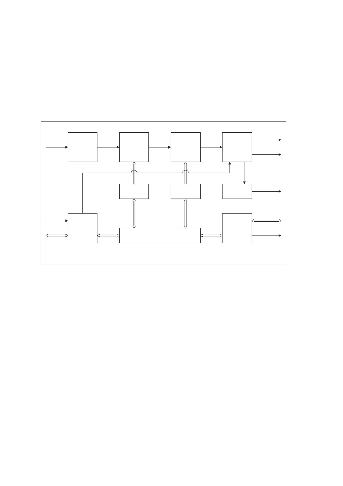
12.2 AC Module
The AC module accepts an input of 115/230VAC 50/60Hz nominal, and
provides two regulated 28VDC outputs: high current for the PA, and low
current for the reciter.
The main circuit blocks are shown in Figure 12.3 below, and are described
in more detail in the paragraphs which follow.
EMC Filter,
Protection, and AC
Switch
The AC input is fed first to an EMC filter consisting of two common-mode
and two differential-mode filters. The input voltage is monitored, and if it
is within the specified voltage range, a “mains OK” signal is sent to the
microprocessor via an opto-coupler. If the mains input voltage is outside the
specified range, the power factor stage is inhibited to protect the AC
converter from damage.
An MOV is fitted between line and phase to clamp low energy noise on the
line. A 10A fuse is also fitted for additional safety. If the fuse blows, it
disconnects the PMU from the mains. Inrush current control is provided by
a high power resistor, which is bypassed by a relay when the PMU is
powered up.
Power Factor
Correction (PFC)
The filtered AC input is fed to this boost power supply where the active
power factor correction circuit converts it to the regulated 400VDC output.
This stage is fully protected from overload and short circuit by the power
supply control circuitry.
Figure 12.3 PMU AC module block diagram
EMC Filter,
Protection,
& AC Switch
Power Factor
Correction
(PFC)
High Voltage
to DC
(HVDC)
System
Interface
and
Fan Control
PFC Control HVDC Control
Auxiliary
Power Supply*
Current Sense
and
Output Filter
Interface to
DC Module
Microprocessor
AC I/P
115/230V
50/60Hz
DC
*optional (mounted on DC module)
Control &
Monitor
28VDC O/P
(PA)
DC O/P
13.65/27.3/54.6V
28VDC O/P
(Reciter)
System
Control Bus
Fan

 Loading...


