TB8100 Service Manual Power Amplifier Board Replacement 189
© Tait Electronics Limited September 2006
3. If the ground plate d is already soldered to the shield wall:
■ fit the N-type connector and tighten the two M3 Torx screws to
the correct torque
■ solder the N-type connector to the PCB.
If the ground plate is not already soldered to the shield wall:
■ fit the ground plate and N-type connector to the heatsink,
ensuring that the tab on the ground plate fits through the slot in
the shield wall
■ tighten the two M3 Torx screws to the correct torque
■ solder the N-type connector to the PCB
■ solder the tag on the ground plate to the inside of the shield wall.
Note In both cases make sure that the ground plate sits flat against the
base of the N-type connector, otherwise the cover may not fit cor-
rectly.
4. Replace the RF links
c and bridging links b.
5. Refit the shield lid and resolder the two tabs.
6. On a 12V PA, refit the boost regulator board (as described in
“Replacing the Boost Regulator Board in a 12V PA” on page 193).
7. Refit the cover.
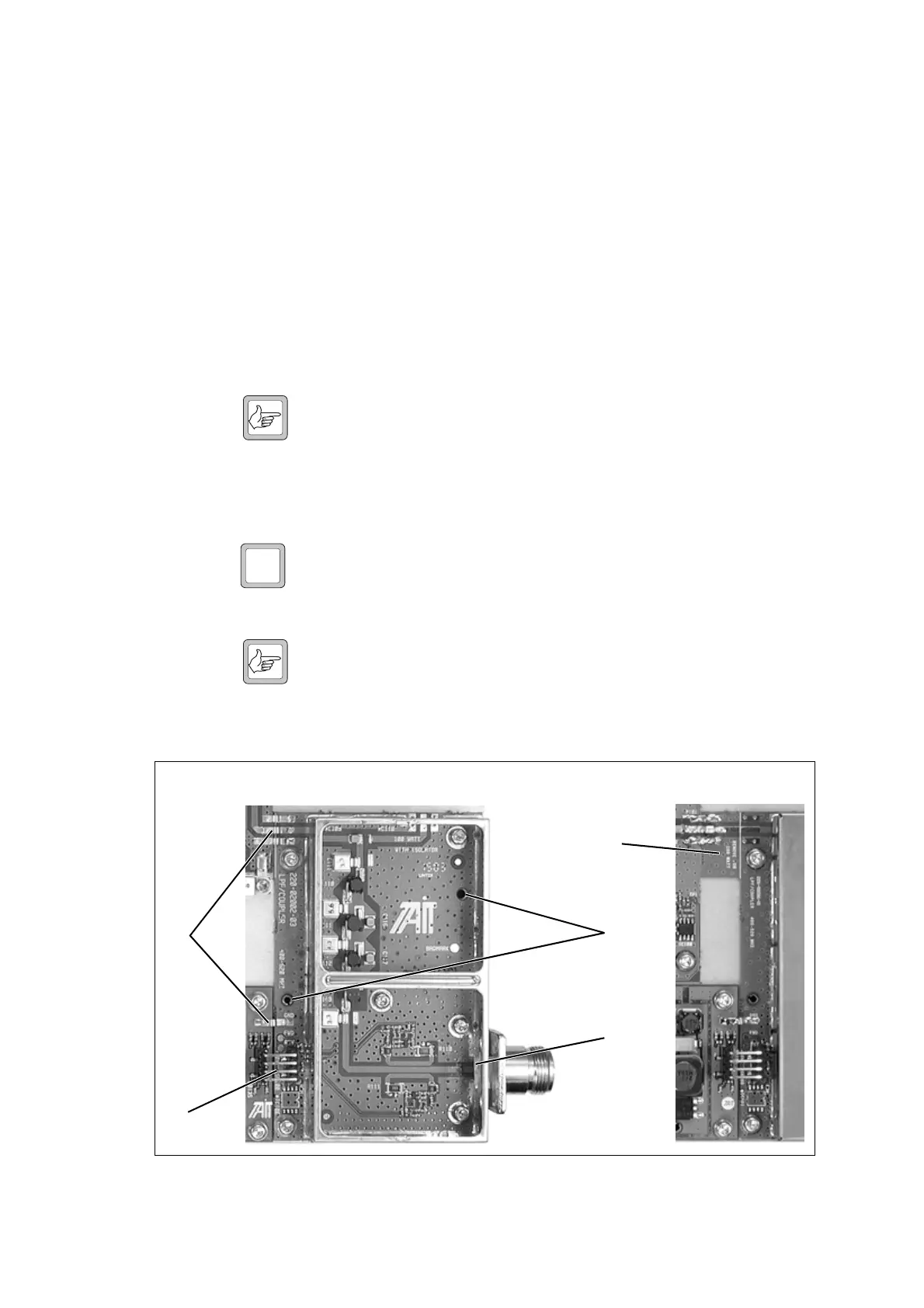
Note If you are fitting a new board, make sure that the RF input tab
f
is left in place for a 5W or 50W PA, and removed for a 100W PA.
If you have to remove the tab, cut it off cleanly with a sharp cut-
ting tool (such as tin snips or a guillotine).
12V
Figure 10.6 Replacing the LPF/directional coupler board
b
c
d
e
f
100W PA 5W and 50W PA

 Loading...


