176 Power Amplifier Disassembly and Reassembly TB8100 Service Manual
© Tait Electronics Limited September 2006
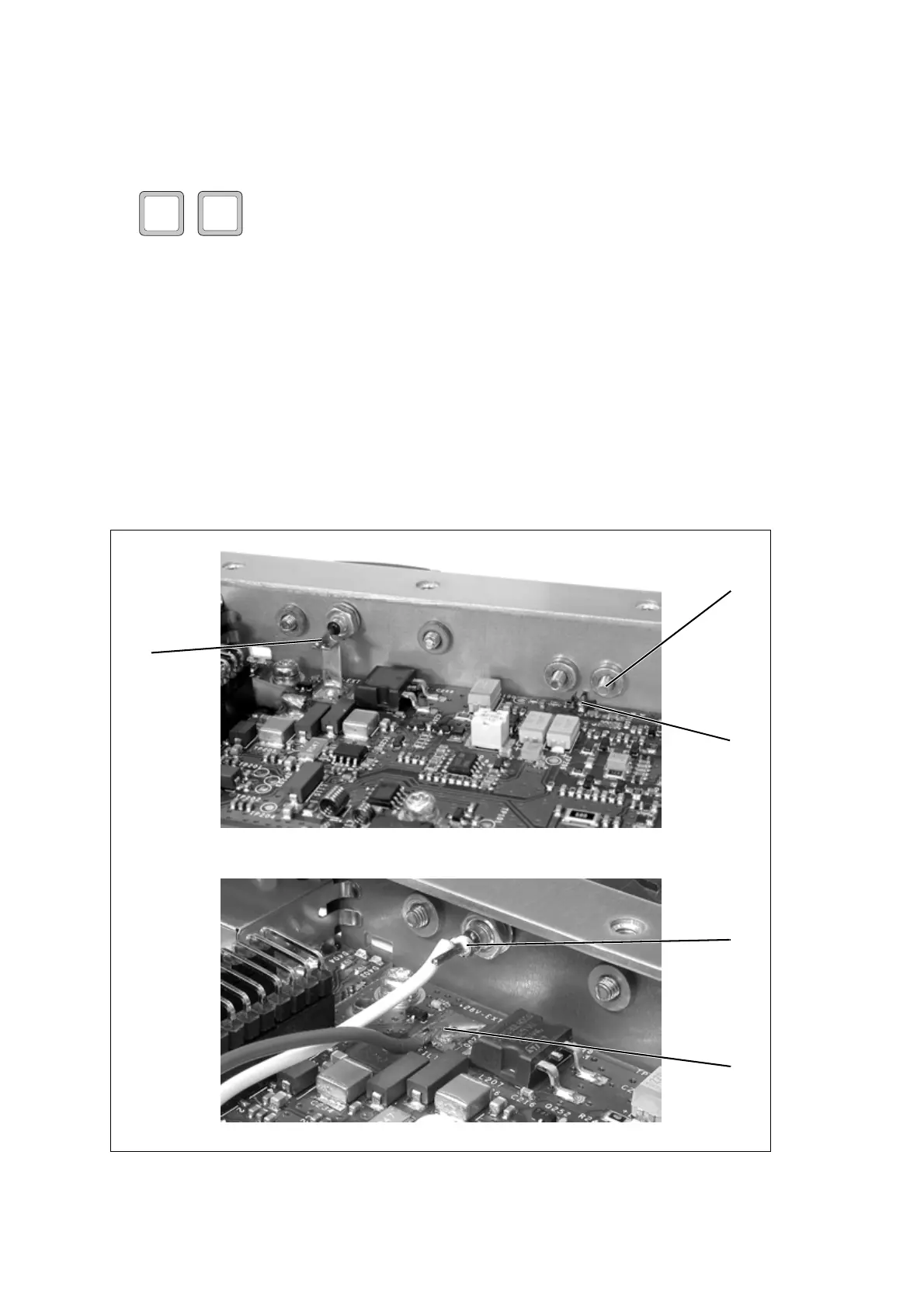
9.3 Removing the Front Panel
The circled numbers in the following instructions refer to Figure 9.2.
1. On a 28V PA, disconnect the +28VDC power feed by desoldering
the feedthrough capacitor from the metal strap
b soldered to the 6W
board. On a 12V PA, desolder the white DC output wire
c from
the feedthrough capacitor, and desolder the red DC output wire
d
from the 6W board.
2. Remove the four M2.5 Torx screws
e securing the SMA connector
to the heatsink and to the front panel.
3. Desolder the centre pin of the SMA connector
f from the 6W board
and remove the connector. Ensure that C100 and L100 are not
affected.
4. Remove the M3 Torx screws securing the front panel to the heatsink
and remove the panel.
28V
12V
Figure 9.2 Removing the front panel
e
f
b
x4
28V PA
12V PA
c
d
12V PA

 Loading...


