TB8100 Service Manual Power Amplifier Circuit Description 123
© Tait Electronics Limited September 2006
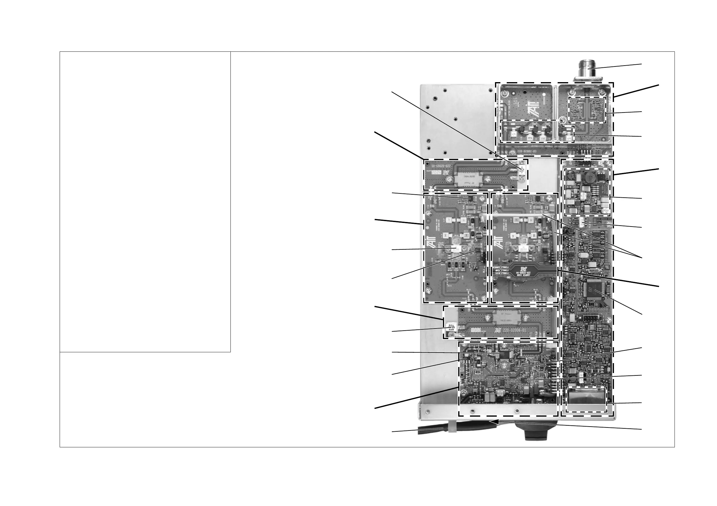
Figure 7.3 Identifying the circuitry on the 28V PA boards
b
RF output
c
low pass filter/directional coupler board
d
directional coupler
e
low pass filter
f
control board
g
power supply
h
ambient air temperature board
i
28VDC power feed
j
60W board
1)
microprocessor
1!
6W board temperature sense
1@
6W driver transistor drain current sense
1#
I
2
C signal filtering
1$
RF input (obscured)
1%
28VDC input
1^
6W board
1&
pre-driver transistor
1*
6W driver transistor
1(
termination resistor (50Ω load)
2)
splitter board
2!
60W board temperature sense
2@
60W final transistor
2#
60W board
2$
60W final transistor drain current sense
2%
combiner board
2^
termination resistor (50Ω load)
Note:
This drawing shows a 100W UHF (H-band) PA. The configuration of
other models is shown in Figure 8.1 on page 130 and Figure 8.2 on
page 131.
d
e
h
f
j
1)
1!
1@
1#
b
1$
c
g
1%
1^
1&
1*
1(
2)
2!
2@
2#
2$
2%
2^
i

 Loading...


