TB8100 Service Manual Power Management Unit Circuit Description 203
© Tait Electronics Limited September 2006
12.1 Microprocessor Control Circuitry
The microprocessor on the HVDC control card monitors and controls the
operation of the PMU. If any of the monitored conditions exceeds its
normal range of values, the microprocessor will generate an alarm and take
appropriate action, depending on the configuration of the PMU. The
software also automatically detects the PMU configuration and controls the
PMU accordingly.
The alarms and diagnostic functions are accessed through I
2
C bus messages
on the system control bus via the reciter, control panel and Service Kit.
The microprocessor also calibrates the output voltage to the required
specification. This information is stored in EEPROM memory during
factory run-up. The output voltage of an uncalibrated PMU is 26.5VDC.
Figure 12.2 on page 204 shows the control signal and power connections to
and from the microprocessor. These are described in more detail in the
paragraphs which follow.
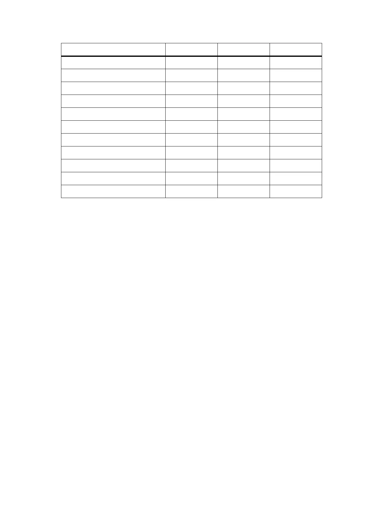
Board and Card Name AC PMU DC PMU AC and DC PMU
DC converter board fitted fitted
DC input filter card fitted fitted
DC control card fitted fitted
battery control card fitted fitted
DC output filter board
a
fitted
DC microprocessor card
b
fitted
AC converter board fitted fitted
HVDC control and microprocessor card fitted fitted
PFC control card fitted fitted
standby power supply card
c
fitted fitted
auxiliary power supply board
d
optional optional optional
a. This is the AC converter board as used in a DC PMU. Only the current sense and output filter circuitry is placed on
this board.
b. This is the HVDC control and microprocessor card as used in a DC PMU. Only the feedback and microprocessor
circuitry is placed on this card.
c. You must fit the appropriate model card to match the DC input voltage of the PMU (i.e. 12VDC, 24VDC or 48VDC
nominal). This card was optional on PMUs manufactured before February 2006.
d. The output voltage is dependent on the model of board - there is a different model board for each output voltage
(i.e. 13.65VDC, 27.3VDC or 54.6VDC).

 Loading...


