TB8100 Service Manual Power Management Unit Circuit Description 213
© Tait Electronics Limited September 2006
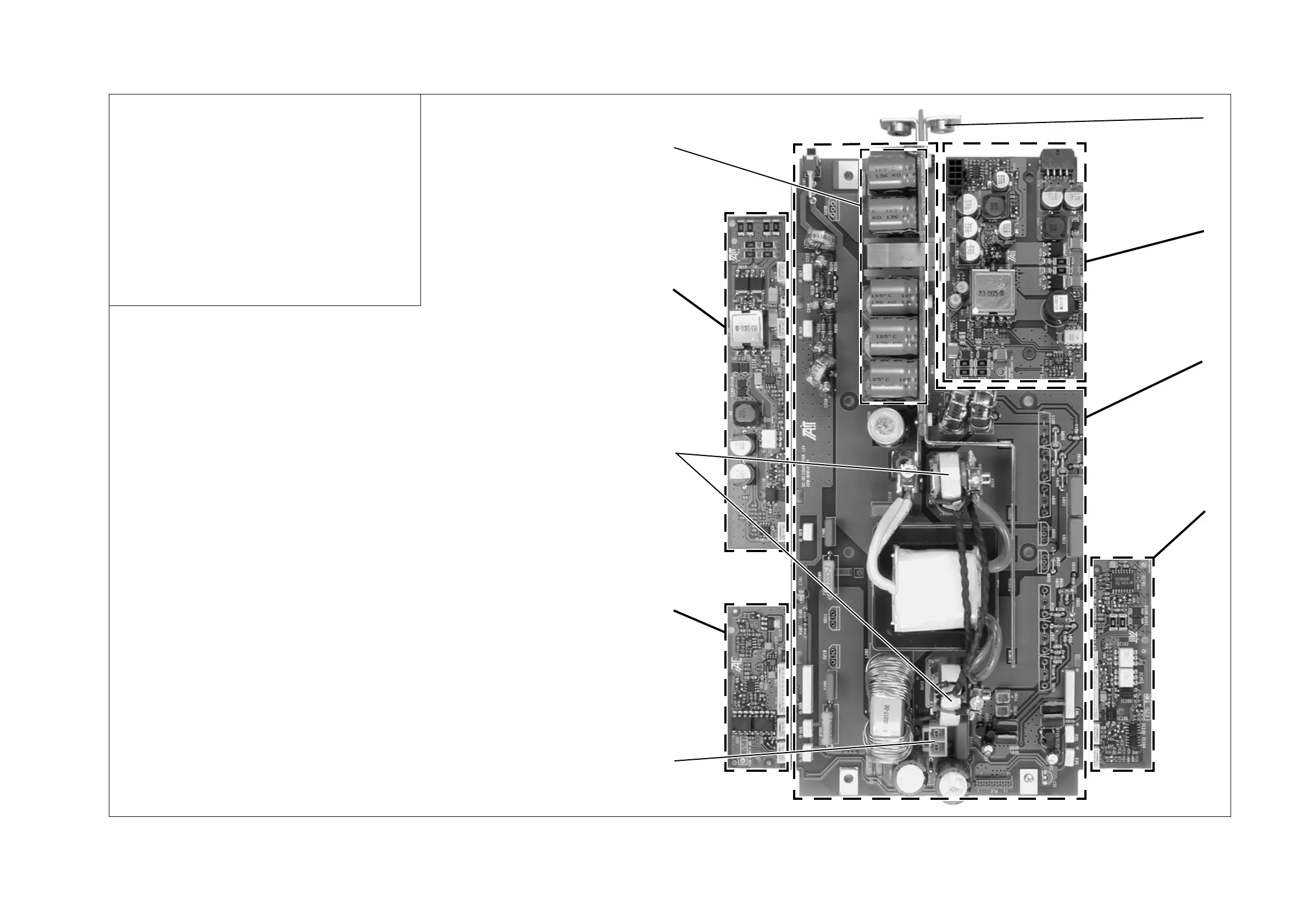
Figure 12.6 Identifying the circuitry in the DC module
b
DC input
c
auxiliary power supply
d
DC power converter
e
DC control
f
output to the current sense and output filter circuitry on the
AC converter board
g
battery control
h
current transformer
i
standby power supply
j
EMC filter and protection
Note:
In order to show as much of the circuitry as possible in the
photograph, the heatsinks and the components normally
attached to them are not fitted, and the plug-in cards are not
plugged in.
b
c
d
e
f
g
h
i
j
12V DC module shown

 Loading...


