160 Power Amplifier Fault Finding TB8100 Service Manual
© Tait Electronics Limited September 2006
8.10 Splitter and Combiner Boards (100W PA Only)
These checks will identify any faults present in:
■ the continuity of the boards
■ the splitter and combiner modules
■ the termination resistors.
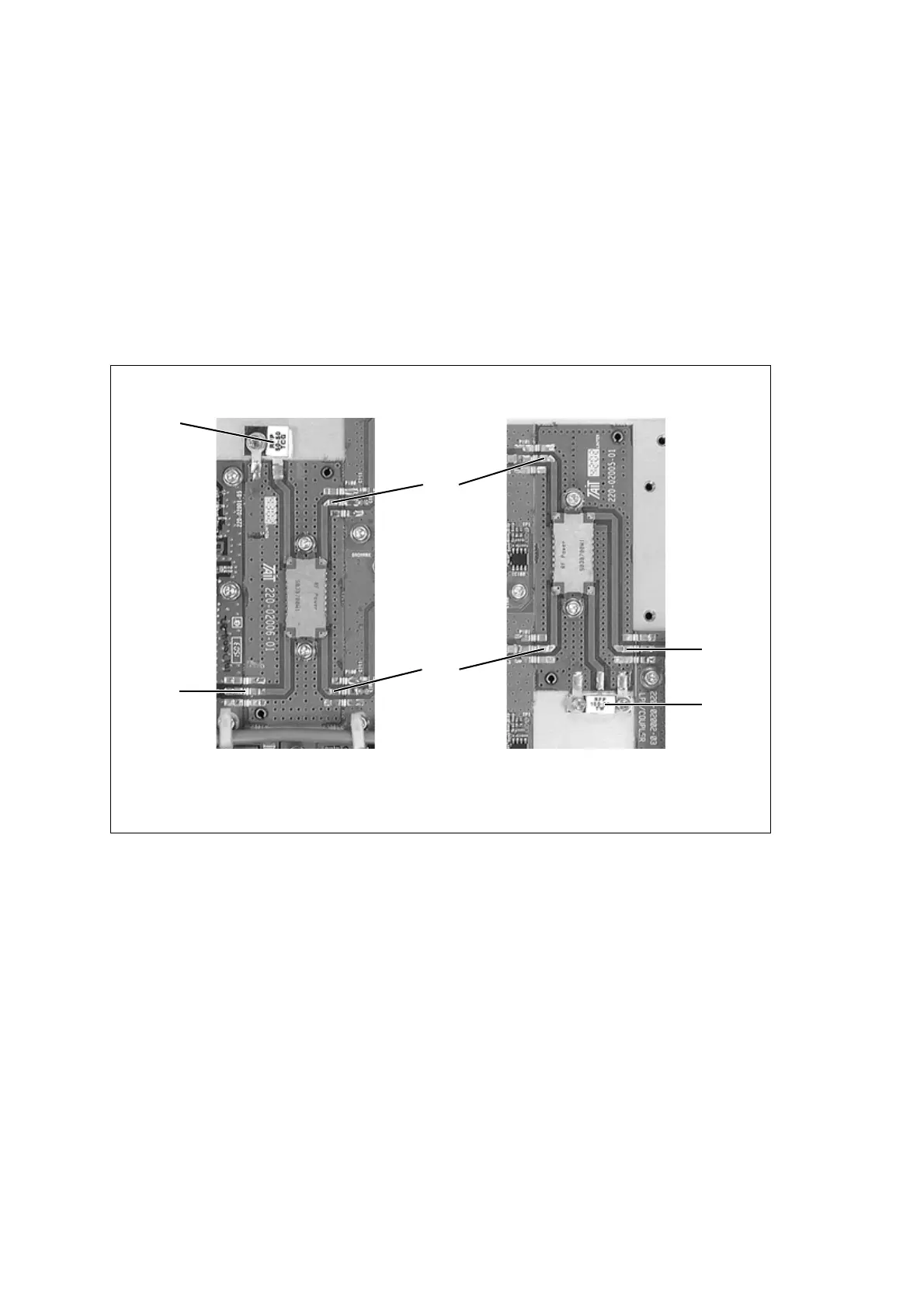
Figure 8.12 shows the location of the test points on the splitter and
combiner boards.
Task 1 —
Check the Splitter
Board
1. Check the DC continuity from the input to port 2, and from the ter-
mination resistor to port 1. If there is continuity, go to Step 3. If
there is not, go to Step 2.
2. Check for faulty solder joints between the splitter and the PCB. If
the solder joints are not faulty, replace the splitter board. If there is a
faulty joint, repair as necessary and repeat Step 1. If there is still no
continuity, replace the splitter board.
3. Check that there is no DC short to ground on each of the four ports.
If there is a short, replace the splitter board. If there is not, go to
Step 4.
Figure 8.12 Location of test points on the splitter and combiner boards
Splitter Combiner
Some models of PA have an SMD termination
resistor on the splitter board.
termination
input
port 1
port 2
termination
output

 Loading...


