TB8100 Service Manual Power Amplifier Board Replacement 183
© Tait Electronics Limited September 2006
3. Refit the board, following the removal instructions in reverse order.
Note Before tightening the screws, press the board down over the locat-
ing pins so that it is firmly seated against the heatsink. Then
tighten the M3 Torx screws to the correct torque.
4. Progressively tighten each 4–40 UNC screw, alternating from side to
side, to the correct torque. Retorque the screws after eight hours of
operation.
5. Refit the cover.
Refitting a New
Board and
Transistor
Use the following instructions if you are fitting a new 60W board, a new
RF power transistor, or have disturbed any of the solder joints around the
transistor.
1. Remove any old heatsink compound from the heatsink.
2. Refit the board, following the removal instructions in reverse order.
Note Before tightening the screws, press the board down over the locat-
ing pins so that it is firmly seated against the heatsink. Then
tighten the M3 Torx screws to the correct torque.
3. Fit the new RF power transistor as described in the “Refitting”
section of “Replacing the 60W RF Power Transistor” on page 184.
4. Refit the cover.
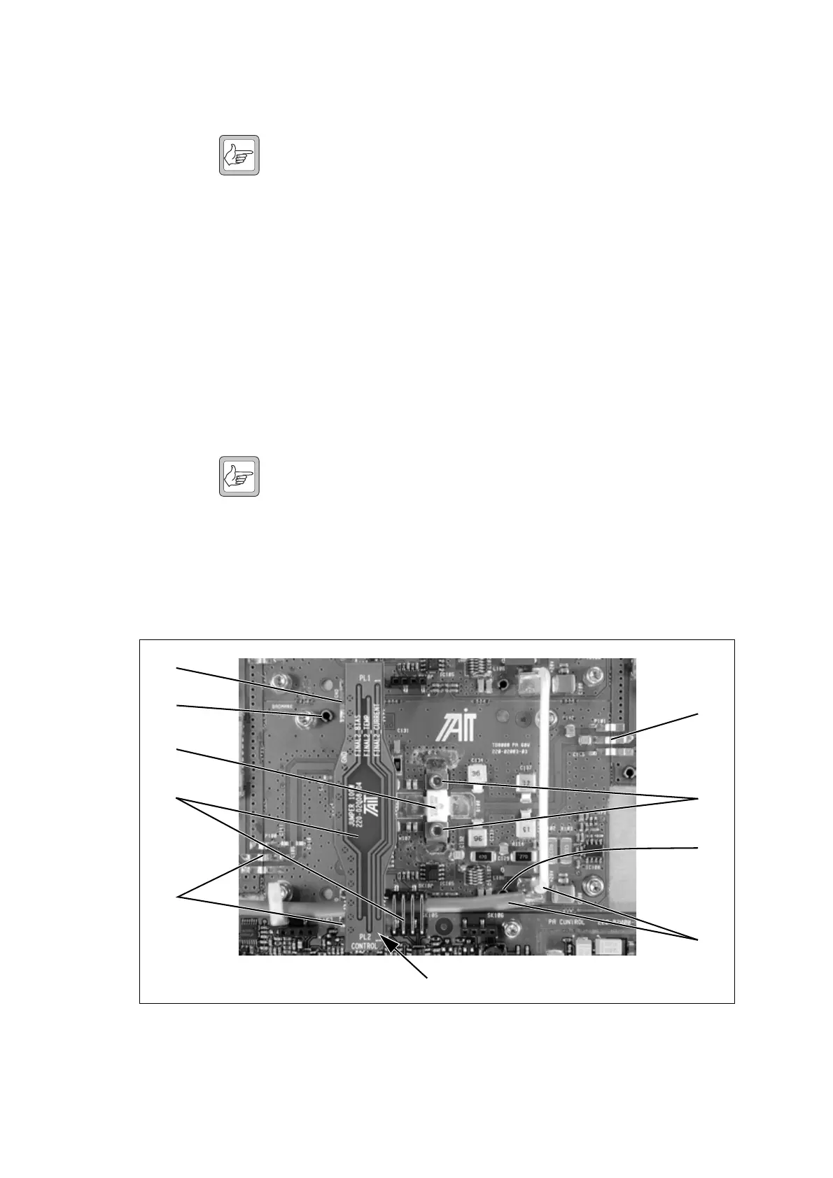
Figure 10.3 Replacing the 60W board
b
c
d
d
f
e
d
g
g
ensure correct orientation when refitting

 Loading...


