TB8100 Service Manual Power Amplifier Board Replacement 191
© Tait Electronics Limited September 2006
Refitting 1. Ensure the heatsink and bottom of the board are clean. Remove any
old heatsink compound.
2. Apply a thin layer of fresh heatsink compound (Dow-Corning 340 or
equivalent) to the bottom of the board underneath the splitter or
combiner. Use as little as possible, while still covering the whole of
the mounting area of the component.
3. Refit the board onto the heatsink, ensuring it is correctly positioned
on the locating pins.
4. Secure the board to the heatsink with the M3 Torx screws (and M2
Pozidriv on VHF) and tighten to the correct torque.
Important Do not overtighten the M2 Pozidriv screws or you may
strip the threads.
Note Some models of PA have an SMD termination resistor. If the PA
under repair has an SMD resistor, proceed to Step 10.
5. Apply a small amount of heatsink compound to the termination
resistor mounting surface. Use as little as possible to provide a very
thin, but even, film over the entire mounting surface.
6. Place the resistor on the heatsink and ensure the tab is flush with the
surface of the PCB.
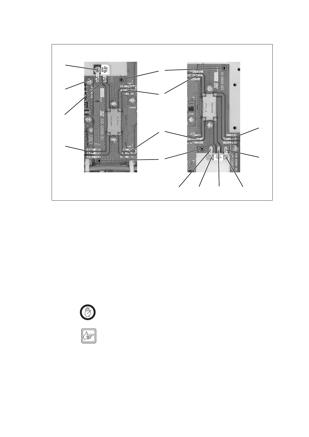
Figure 10.7 Replacing the splitter/combiner boards
e
d
Splitter Combiner
b
b
f
f
b
b
c
eecd
d

 Loading...


