TB8100 Service Manual Reciter Fault Finding 91
© Tait Electronics Limited September 2006
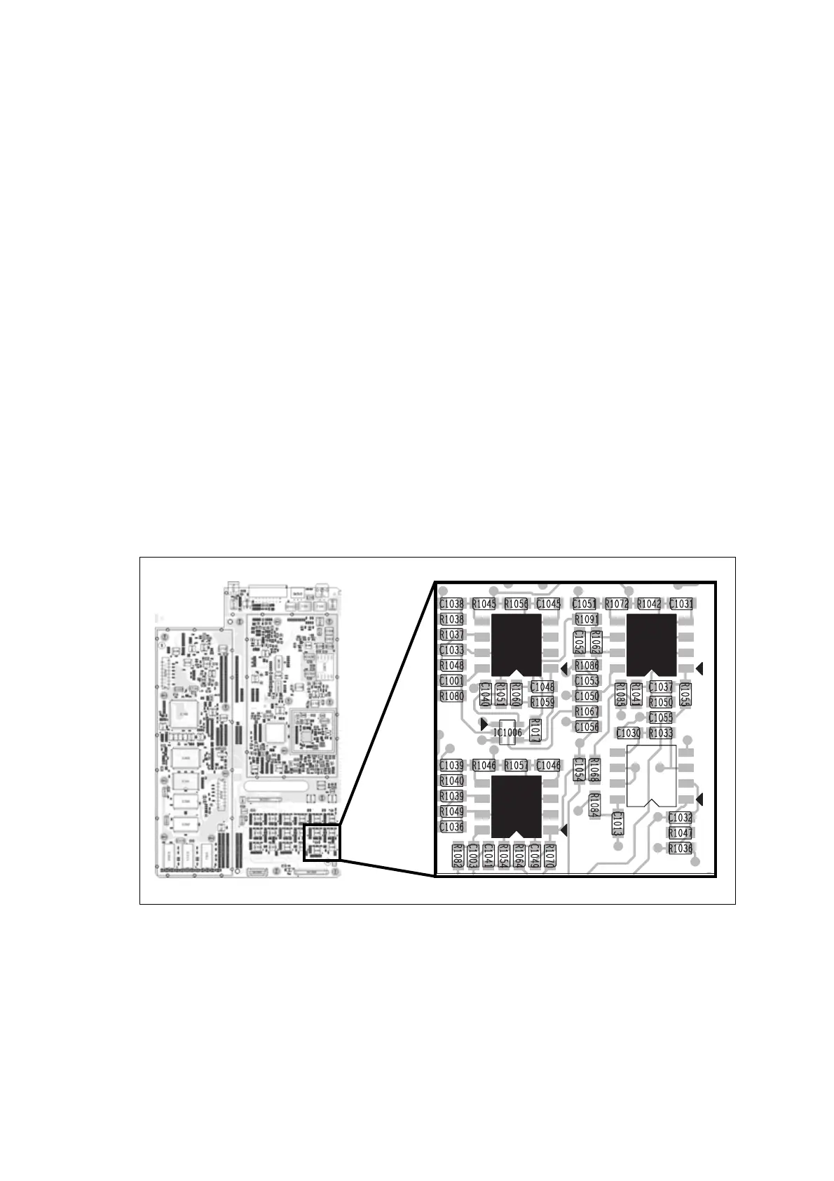
8. Measure the audio voltages at the following test points on the digital
board:
balanced line out IC1020 pin 1
IC1026 pin 1
unbalanced line out IC1005 pin 1
IC1026 pin 7.
Both voltages should be approximately 1V
pp
. If the voltages are
greater than 1V
pp
, the digital board is faulty. Return the complete
reciter to your nearest CSO for repair or replacement. If the voltages
are 1V
pp
or less, replace the system interface board.
9. Measure the audio voltages at the following test points on the digital
board:
balanced line out IC1020 pin 1
IC1026 pin 1
unbalanced line out IC1005 pin 1
IC1026 pin 7.
Both voltages should be approximately 1V
pp
. If the voltages are 1V
pp
or higher, replace the system interface board. If the voltages are less
than 1V
pp
, the digital board is faulty. Return the complete reciter to
your nearest CSO for repair or replacement.
Figure 3.7 Location of audio test points on the digital board
IC1030
IC1026
IC1005
IC1020
1
7
1
1

 Loading...


