244 Power Management Unit Fault Finding TB8100 Service Manual
© Tait Electronics Limited September 2006
Task 4 —
Check Gate Signals
of PFC and HVDC
FETs
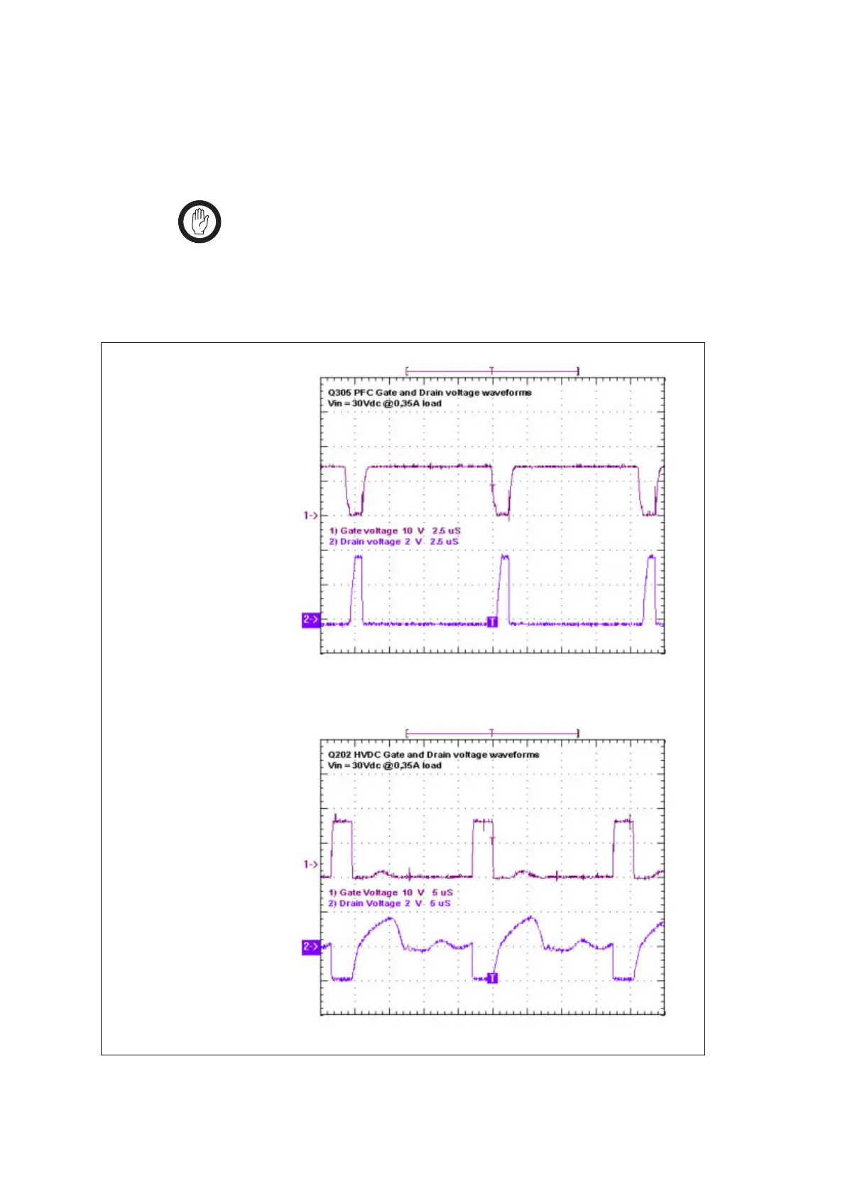
1. Check the gate signals (gate-to-source) of all four FETs (Q201,
Q202, Q305, Q306) individually. If the signals match the wave
forms shown in Figure 13.12, go to Step 2. If they do not, replace
the AC module and go to “Final Tasks” on page 247.
Important Ensure the oscilloscope is floating before earthing the oscil-
loscope at the source of Q201. Do not test the
gate-to-source signal of both Q201 and Q202 simultane-
ously. If the oscilloscope is not floating, do not test the
gate-to-source signal of Q201.
Figure 13.12 Typical gate-source and drain-source waveforms for FETs
Q305 and Q306
Q201 and Q202

 Loading...


