TB8100 Service Manual Power Management Unit Fault Finding 217
© Tait Electronics Limited September 2006
13.2 Identifying the PMU
You can identify the model and hardware configuration of a PMU by
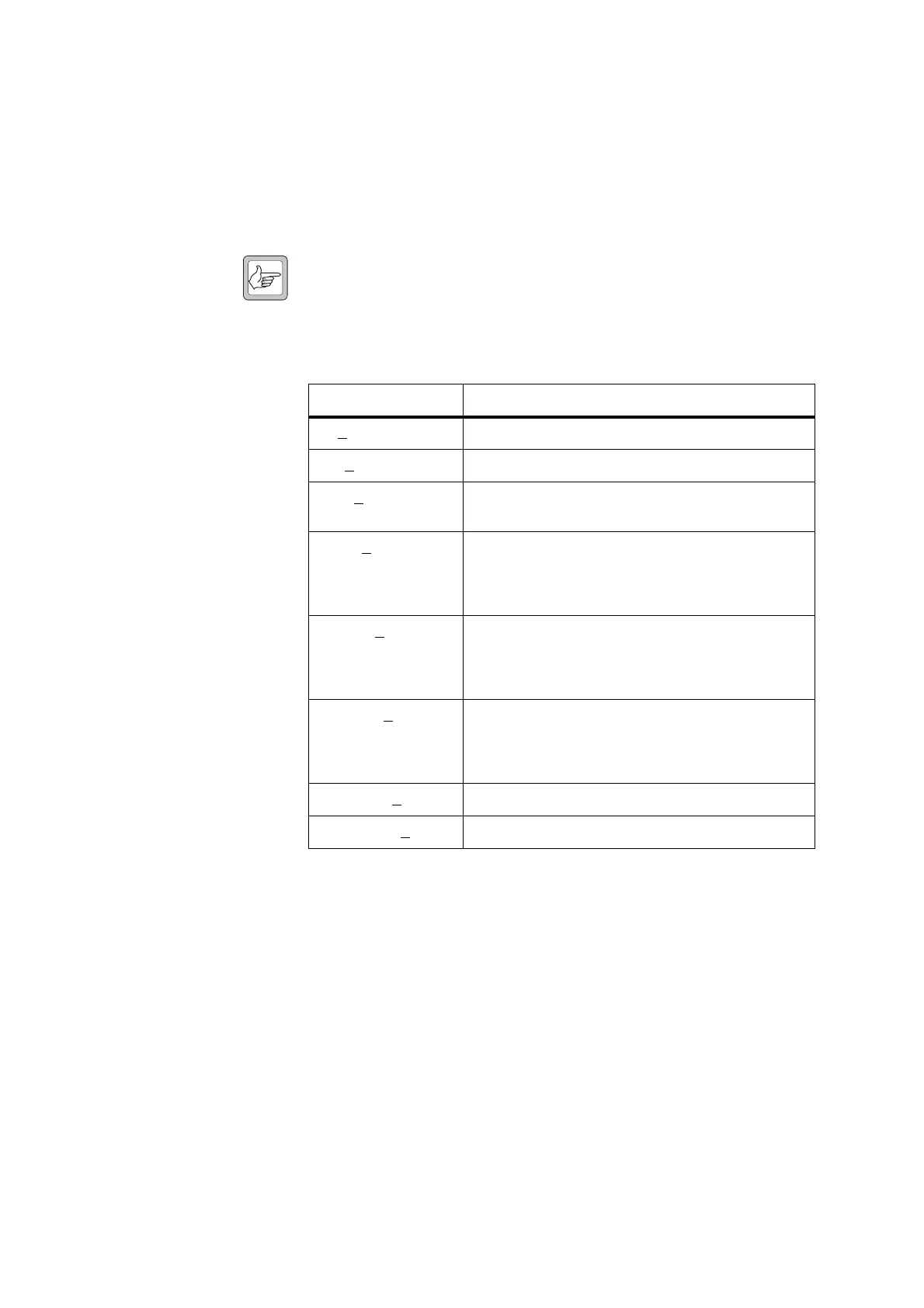
referring to the product code printed on a label on the rear panel. The
meaning of each character in the product code is explained in the table
below.
Note This explanation of PMU product codes is not intended to suggest
that any combination of features is necessarily available in any one
PMU. Consult your nearest Tait Dealer or Customer Service
Organisation (CSO) for more information regarding the availabil-
ity of specific models and options.
13.2.1 Colour Coding of Circuit Boards and Cards
The DC converter board and standby power supply card are colour-coded
according to their nominal input voltage. The auxiliary power supply board
is also colour-coded according to its nominal output voltage. The colours
used are as follows:
■ 12VDC – green
■ 24VDC – yellow
■ 48VDC – red.
Product Code Description
TBAX
XXX-XXXX 3 = PMU
TBA3X
XX-XXXX 0 = default
TBA3XX
X-XXXX 0 = AC module not fitted
A = AC module fitted
TBA3XXX-XXXX 0 = DC module not fitted
1 = 12V DC module fitted
2 = 24V DC module fitted
4 = 48V DC module fitted
TBA3XXX-XXXX 0 = standby power supply card not fitted
1 = 12VDC standby power supply card fitted
2 = 24VDC standby power supply card fitted
4 = 48VDC standby power supply card fitted
TBA3XXX-XXXX 0 = auxiliary power supply board not fitted
1 = 12VDC auxiliary power supply board fitted
2 = 24VDC auxiliary power supply board fitted
4 = 48VDC auxiliary power supply board fitted
TBA3XXX-XXXX 0 = default
TBA3XXX-XXXX
0 = default

 Loading...


