252 Power Management Unit Disassembly and Reassembly TB8100 Service Manual
© Tait Electronics Limited September 2006
14.3 Screw Torque Settings
The recommended torque settings for the screws used in the PMU are as
follows:
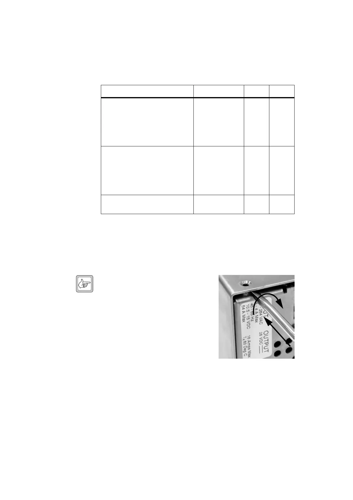
14.4 Removing the Top and Bottom Covers
1. Remove the four M3 Torx screws securing the top cover to the front
and rear panels. Lift off the top cover.
Note If the top cover is difficult to
move, we suggest you lift one
end of the cover away from the
end panel with a flat-blade
screwdriver. The cover should
then be loose enough to lift off.
2. Turn the PMU over and remove
the four M3 Torx screws securing
the bottom cover to the front and
rear panels. Lift off the bottom
cover.
Location / Function Torque Driver Size
■ securing the front and rear panels to
the heatsinks
■ securing the AC and DC converter
boards to the heatsinks
■ securing the bus bars to the DC
converter board
2.0N·m / 18lbf·in T20 M4
■ securing the top and bottom covers
to the front and rear panels
■ securing the handle to the front
panel
■ securing the DC input filter card to
the bus bars
0.5N·m / 4.5lbf·in T10 M3
securing the 500W DC transformer
primary wires into their terminals
1.8N·m / 16lbf·in flat blade

 Loading...


