TB8100 Service Manual Power Management Unit Circuit Description 211
© Tait Electronics Limited September 2006
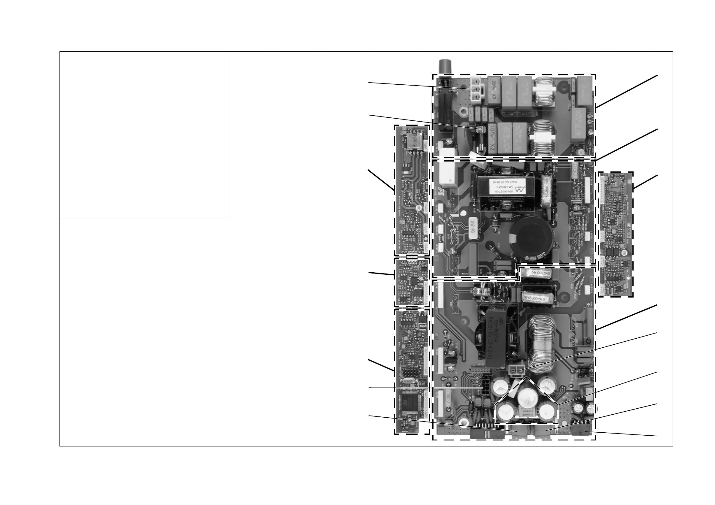
Figure 12.5 Identifying the circuitry in the AC module
b
EMC filter, protection and AC switch
c
power factor correction (PFC)
d
PFC control
e
high voltage to DC converter
f
28VDC input from the DC converter board
g
current sense and output filter
h
28VDC output for PA
i
28VDC output for reciter
j
28VDC output to auxiliary power supply board
1)
microprocessor control
1!
AC and DC voltage and current control
1@
HVDC control
1#
fuse (10A 250V)
1$
AC mains input
Note:
In order to show as much of the circuitry as possible in the
photograph, the heatsinks and the components normally
attached to them are not fitted, and the plug-in cards are not
plugged in.
b
c
d
e
g
i
h
h
1)
1!
1@
1$
f
j
1#

 Loading...


