NOTE. The Logic qualification option is not available on DPO5000B and MSO5000B Series instruments.
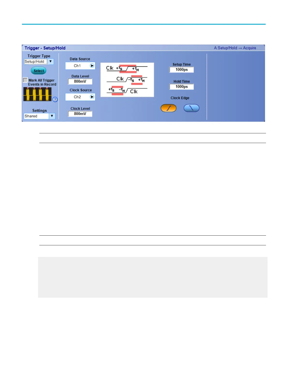
Behavior. Use the Setup and Hold violation trigger to trigger on setup and hold time violations. When you click on the trigger
window controls, the trigger graphic shows the trigger sequence.
The setup and hold times define a violation region relative to a clock. Data is considered to be invalid in the violation region. The
instrument monitors the data and clock sources. When a clock edge occurs, the instrument checks the data channel for
transitions within the violation region. If any violations occur, the instrument triggers with the trigger point located at the clock
edge. The setup and hold values can be positive or negative. The trigger can also be qualified by the logical state of other
channels or by a bus pattern (MSO70000C/DX Series only).
The minimum setup and hold time is 2 ns. Negative setup and hold times skew the violation region to locate it before or after the
clock edge. The instrument can detect and trigger on violations of time ranges that are before or after the clock.
Use one of the channel inputs as the clock signal and a second channel input as the data input. The clocking and data levels are
used to determine if a clock or data transition has occurred.
Not recommended for use with iCapture inputs.
NOTE. You have the option to add user-defined labels for analog, reference, bus, and digital sources.
What do you want to do next?
Learn more about other trigger types.
Return to the Trigger Setup control window.
Trigger graphic
The trigger graphic displays a visual indicator of the trigger criteria. Depending on the trigger type, the instrument will update the
graphic as you define the trigger parameters.
Trigger setups
426 DPO70000SX, MSO/DPO70000DX, MSO/DPO70000C, DPO7000C, and MSO/DPO5000B Series
 Loading...


