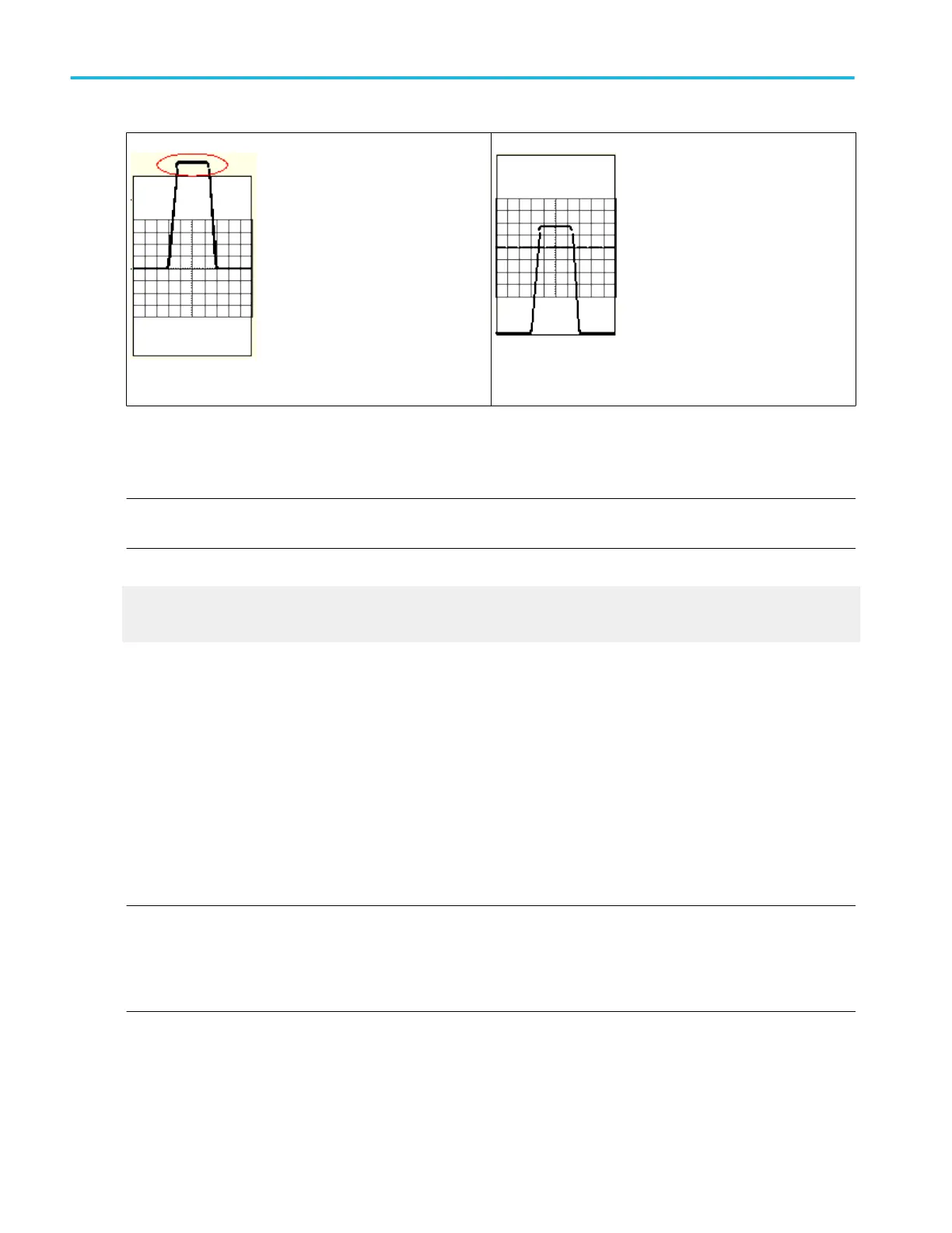
Figure 18: Acquired waveform
Figure 19: Adjusted horizontal scale
Set the horizontal scale, position, and resolution (record length) to include the acquired waveform record waveform attributes of
interest with good sampling density on the waveform. These settings define the horizontal acquisition window, described
inHorizontal Acquisition Window Considerations .
NOTE. The terms vertical acquisition window and horizontal acquisition window refer to the vertical and horizontal range of the
segment of the input signal that the acquisition system acquires. The terms do not refer to any display windows on screen.
What do you want to do next?
Learn about the Vertical Setup Position and Scale controls.
Learn about the Vertical Offset control.
Vertical acquisition window considerations
You can set the vertical scale, position, and offset of each channel independently of other channels. Vertical scale and offset
specify the vertical acquisition window for each channel. Parts of the signal amplitude that fall within the vertical window are
acquired; parts outside (if any) are not.
The offset control subtracts a constant DC level from the input signal before the vertical scale factor is applied, and the vertical
position control adds a constant number of divisions of signal after the scale factor is applied to the resulting difference.
The vertical scale and position controls have the following affects on the vertical acquisition window and the displayed waveform:
The vertical volts per division you set determines the vertical size of the acquisition window, allowing you to scale it to contain all
of a waveform amplitude or only part. Figures A and B below show two vertical acquisition windows that contain the entire
waveform, but only the window in Figure B contains the entire waveform in the graticule on screen.
NOTE. Amplitude-related automatic measurements (for example, peak-to-peak and RMS) will be accurate for vertical windows
like those shown in Figures A and B below because neither waveform is clipped (that is, both waveforms are acquired). But if
signal amplitude were to extend outside the vertical acquisition window, the data acquired is clipped. Clipped data causes
inaccurate results if used in amplitude-related automatic measurements. Clipping also causes inaccurate amplitude values in
waveforms that are stored or exported for use in other programs.
If the scale of a math waveform is changed so that the math waveform is clipped, it will affect the amplitude measurements on
that math waveform as follows:
■
The vertical position adjusts the display of the graticule relative to the vertical acquisition window (position is a display
control). Figure B shows how vertical position moves the waveform graticule vertically in the acquisition window to place the
acquired waveform in the graticule display. That is all position does; it does not determine what data is acquired as do
vertical scale and offset.
Oscilloscope reference
654 DPO70000SX, MSO/DPO70000DX, MSO/DPO70000C, DPO7000C, and MSO/DPO5000B Series
 Loading...


