■
Automatic measurements on communications signals
NOTE. If a standard listed in this manual is not available on your instrument, it is because the configuration or bandwidth of
your instrument cannot test that standard.
Although this oscilloscope is not a calibrated optical reference receiver, you can use it with mask testing to evaluate general
optical signal characteristics and wave shape, using an external O/ E converter.
What do you want to do next?
Learn more about mask testing.
Learn more about eye measurements.
Learn about communication triggering.
Go to mask testing setup.
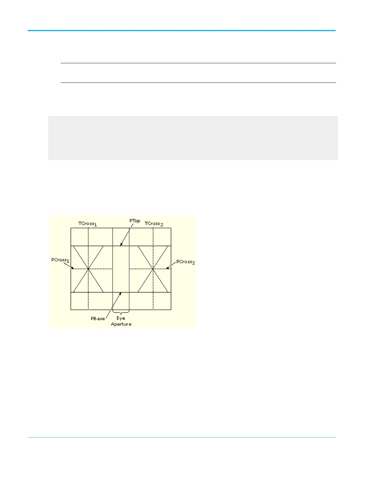
Levels used in taking eye measurements
All eye-diagram measurements are based on the power level, the voltage level, or the time locations of edges within each
acquisition.
The next figure shows the areas of an eye-diagram used to calculate measurements.
P values. The P values include the mean and standard deviation of the vertical location of PTop and PBase. These areas are
used with a specified sample size to statistically measure the following values
1
:
■
PTop Mean. This is the mean value of PTop.
■
PTop Sigma. This is the standard deviation of PTop.
■
PBase Mean. This is the mean value of PBase within the Eye Aperture.
■
PBase Sigma. This is the standard deviation of PBase within the Eye Aperture.
1
The Eye Aperture defaults to the center 20% of the interval from TCross
1
to TCross
2
.
Oscilloscope reference
740 DPO70000SX, MSO/DPO70000DX, MSO/DPO70000C, DPO7000C, and MSO/DPO5000B Series
 Loading...


