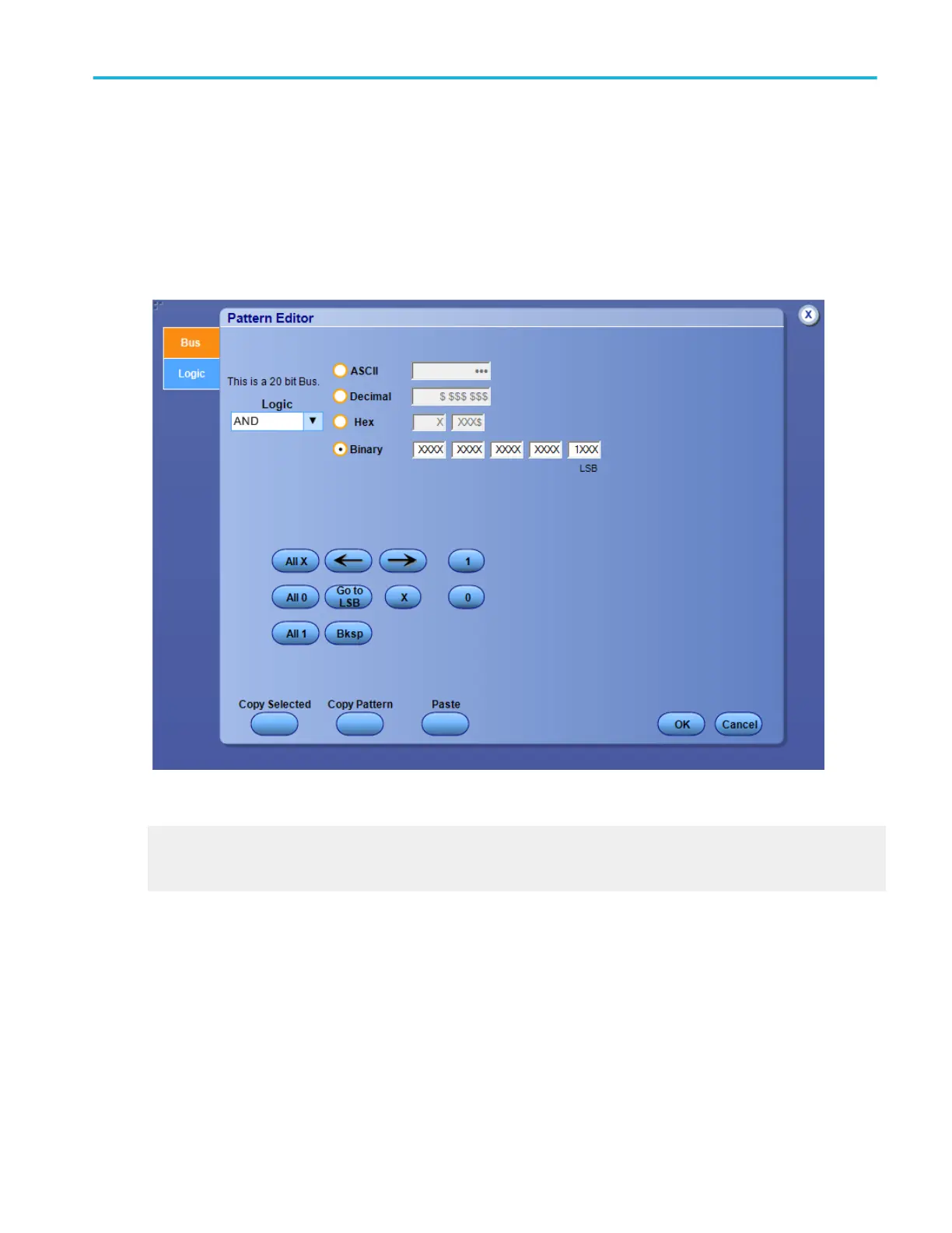
Logic pattern and state pattern editor (bus tab)
Use the controls to set up the Logic Pattern or the Logic State trigger pattern for the instrument to use to detect a bus value.
The maximum pattern size (number of bits) for Logic Pattern or Logic State trigger is 20 bits. The display pattern format is binary,
hexadecimal, ASCII, or decimal. The pattern display format can also be symbolic. The binary pattern uses the symbols 0, 1, and
X (it is a do not care bit and is not case-sensitive). The hexadecimal pattern uses the symbols 0, 1, 2, 3, 4, 5, 6, 7, 8, 9, A, B, C,
D, E, F, and X. Five hexadecimal characters will convey all 20 digital inputs. The characters show up in the binary, hexadecimal,
ASCII, and decimal fields. The non-selected entries are automatically populated with the correct data corresponding to what you
enter in the selected entry field. An X is shown in the field when you do not enter enough characters.
What do you want to do next?
Learn how to set the voltage threshold level for channels used as digital waveforms and to define a pattern.
Learn about bus setups.
Oscilloscope reference
DPO70000SX, MSO/DPO70000DX, MSO/DPO70000C, DPO7000C, and MSO/DPO5000B Series 779
 Loading...


