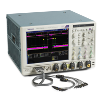
Oscilloscope reference
Functional model
The instrument has four high-level subsystem processes, consisting of both hardware and software functions, and the data that
connects them.
Digital signal acquisition system
This system acquires a waveform record from each input signal you probe. This system consists of the following subsystems:
■
Input Channels. Condition the input signal, primarily through the use of analog hardware, before converting the signal to a
digital format.
■
Trigger System. Recognizes a specific event of interest on the input signal and informs the Time base system of the
occurrence of the trigger event
■
Time base System. Triggers the Acquisition system to start an acquisition cycle. In more general terms, synchronizes the
capturing of digital samples in the Acquisition system to the trigger events generated from the Trigger system.
Acquisition system
This system converts and stores the analog signal to a digital format.
Signal processing and transformation
This system performs transformations or operations on user-specified waveform data (channel, reference, and/or math
waveforms). Automatic measurements, spectral waveforms, and histogram generation are examples of signal processing and
transformation.
Display and UI
This system provides output (and sometimes input) of instrument-data elements in a form suitable to the user and also provides
user input control.
What do you want to do next?
Learn about a process overview of the instrument operation.
Learn about the Acquisition System.
Learn about the Display.
DPO70000SX, MSO/DPO70000DX, MSO/DPO70000C, DPO7000C, and MSO/DPO5000B Series 649

 Loading...


