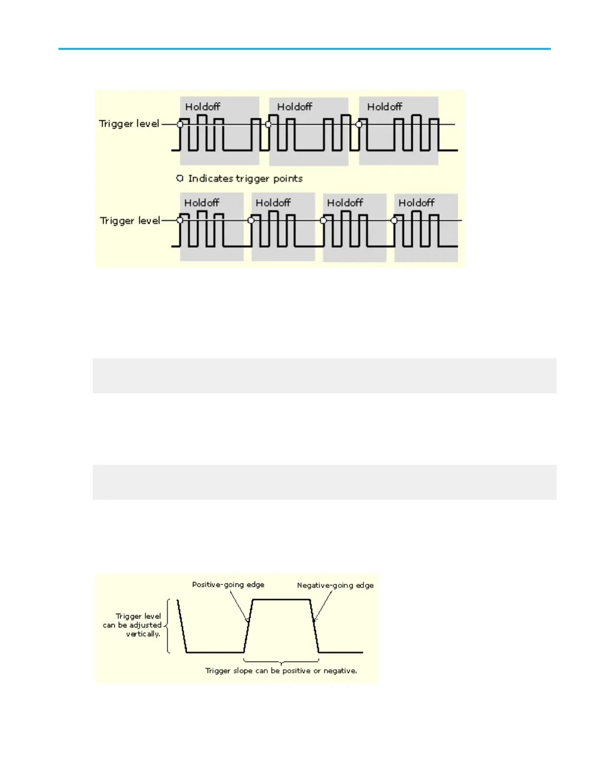
At the longer holdoff time for the top waveform, unstable triggering occurs. With a shorter holdoff set for the bottom waveform,
triggers all occur on the first pulse in the burst to remedy the unstable trigger.
The Holdoff setting range is 1.5 µs (minimum holdoff available) to 12 s (maximum holdoff available). For more information on
how to set holdoff, click here. You can also set a default holdoff. The default holdoff is the general-purpose holdoff for most
applications and varies with the horizontal scale. It is equal to five times the current horizontal scale setting.
Learn about trigger coupling.
Learn about trigger modes.
Trigger coupling
Trigger coupling determines what part of the signal is passed to the trigger circuit. Edge triggering can use all available coupling
types: AC, DC, Low Frequency Rejection, High Frequency Rejection, Noise Rejection, and RF coupling (SX models only). All of
the advanced trigger types use DC coupling only. For a description of each coupling type, click here.
Learn about trigger position.
Learn about trigger holdoff.
Trigger slope and level
The slope control determines whether the instrument finds the trigger point on the rising or the falling edge of a signal. The level
control determines where on that edge the trigger point occurs. See the next figure.
What do you want to do next?
Oscilloscope reference
DPO70000SX, MSO/DPO70000DX, MSO/DPO70000C, DPO7000C, and MSO/DPO5000B Series 667
 Loading...


