4.10 Setting of RGB BUFF Board: 03P9229B
4-55
4.10 Setting of RGB BUFF Board: 03P9229B
When inputting radar video signals to VDR, you should install the optional DVI I/F board
(SLB-FRN4-A), RGB BUFF board (03P9229-B) and RGB connector converter. The
monitor unit MU-201CR is connected with similar DVI interface board (SLB-FRN3-A),
which is not available for shared use.
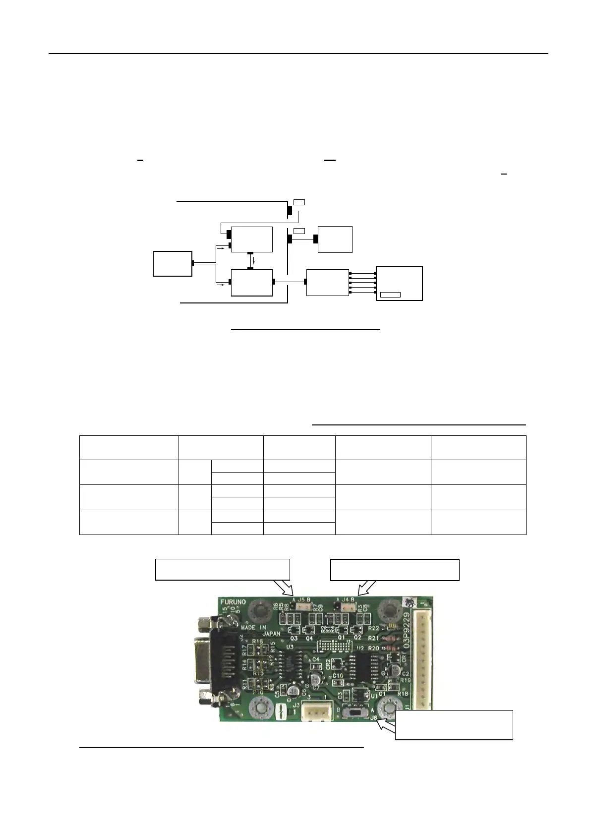
Fig. 4.10.1 Connection of VDR
4.10.1 Jumper Setting
Signals outputted to VDR are R, G and B video signals, and then V and H synchronizeing
signals. The items to be set are the polarity setting of synchronizing signals and input
voltage setting of the RGB BUFF board.
Table 4.10.1 Setting of RGB BUFF Board
Function Jumper Setting
VR-5000
connection setting
Factory setting
A-Comm. Reverse H SYNC
polarity setting
J4
B-Comm. Retain
B-Comm.(Center) B-Comm.
A-Comm. Reverse V SYNC
polarity setting
J5
B-Comm. Retain
B-Comm. (Center) B-Comm.
A - 5 V input Input voltage
selection setting
J6
B - 12 V input
B
(“-5V” is not used.)
B
[A J5 B]: V SYNC polarity
[A J4 B]: H SYNC polarity
[A J6 B]: Selecting Input
volta
e
Fig. 4.10.2 Location of Jumper Plugs on RGB BUFF Board
Note: Comm: Jumper center
DVI I/F p.c.b
RGB BUFF p.c.b
J1(13p)
J2(15p)
J3(3p)
J4(6p)
DVI
J9(10p)
Terminal p.c.b
J615(5p)
+5V/-12V
+12V
R/G/B/VS/HS
R/G/B/VS/HS
J3(DVI)
DVI
RPU-013
MONITOR
RGB CONNECTOR
CONVERTER
R Video
G Video
B Video
V Sync
H Sync
75 Ohm Co-X
VDR
(VR-5000)
Video Port
 Loading...