4.11 Alarm Output Setting
4-61
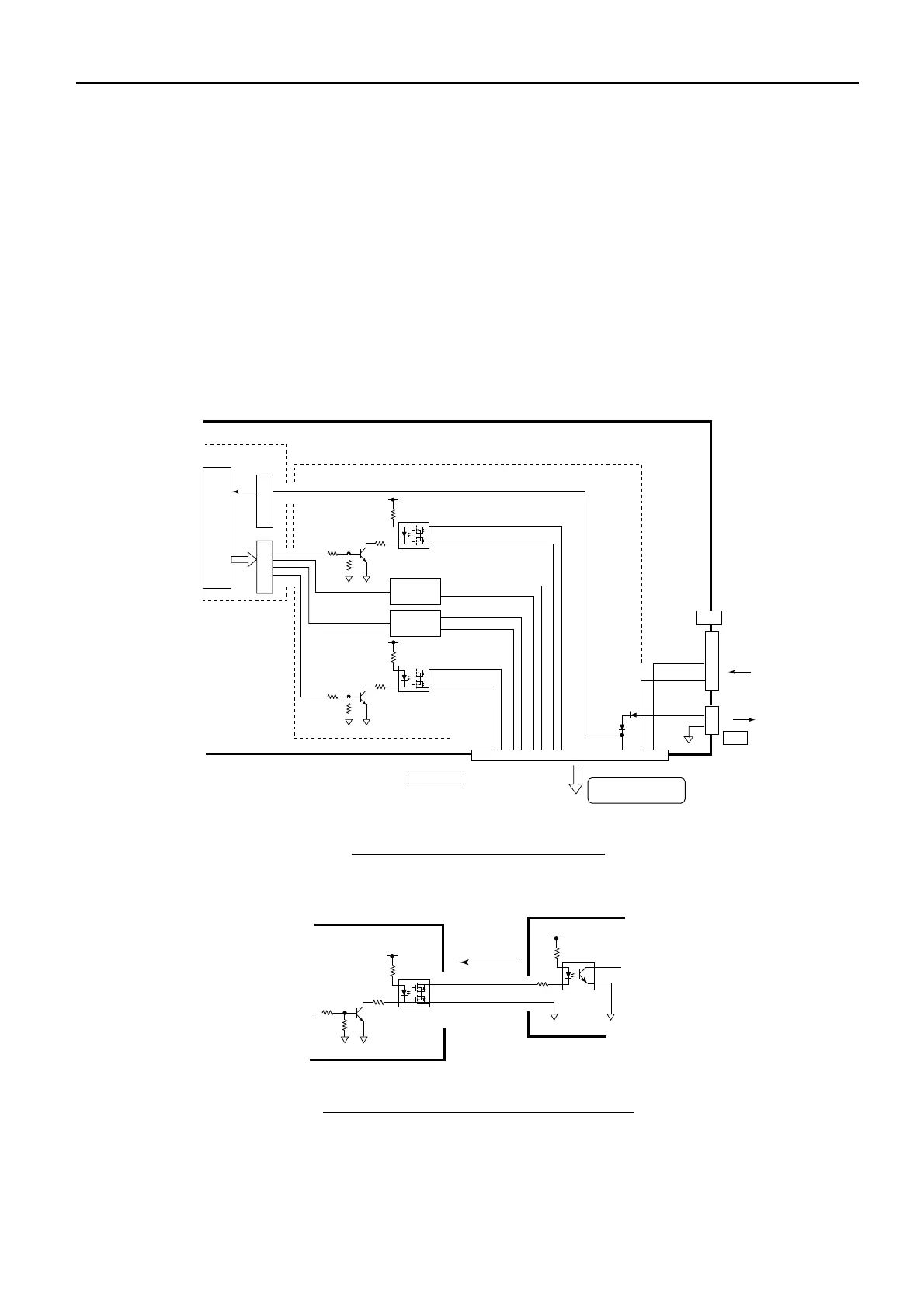
4.11.2 Setting of Alarm Output
This is the setting for outputting alarm detected by the processor unit (RPU-013). There are
four talarm ports. Respective alarm output items are set in [MENU] -> 3-> 6, 7, 8, 9:
ALARM OUT-1, 2, 3, 4.
Operations of the EXT ALARM terminals on the TB board are as follows.
- ALM-1, 2, 3: Normally Close. (During Power Off and Initializing - Close)
Driver is U10-12: PS7241 1B
- ALM-4 : Normally Open. (During Power Off and Initializing - Open)
Driver is U9: TLP176G TP
There is ALARM OUTPUT POLARITY in each setting item of Alarm OUTPU 1 to 4, and
then they can reverse the polarity of the alarm output.
Fig. 4.11.6 ALARM Output Circuit
Fig. 4.11.7 Connection of ALARM Output
4
4
3
3
1
2
1
2
U21
MAIN CPU
ALARM1-0
ALARM 1
ALARM 2
ALARM 3
ALARM 4
ALARM1-1
U12
(PS7241 1B)
ALARM2-0
ALARM2-1
ALARM3-0
ALARM3-1
ALARM4-0
ALARM4-1
U9
(TLP176G TP)
Q4
U22
Q1
I/F
U31
I/F
SYS FAIL H
SYS FAIL C
1
2
1112
J622
J602
GND
SYS ACK H
9
10
RPU-013
SPU p.c.b
Terminal p.c.b
EXT ALARM ACK N
KEY
EXT ALARM
J612
ALARM SYSTEM
KEY
192345678
Same as
above
(U11/Q3)
Same as
above
(U10/Q2)
Normal close
Normal open
4
3
1
2
U12
(PS7241 1B)
1
2
Q4
ALARM SYSTEM
ALARM OUT x-0
ALARM OUT x-1
RPU-013
400V max.
100mA max.
 Loading...