7.3 Processor Unit: RPU-013
7-63
7.3.5 Power board
1. Power supply specifications
The power board differs according to the types of input power supply and antenna
revolving speed. See page.4-64 to 68.
Jumper setting inside the board performs switching between 100 to 115 VAC and 220 to
230 VAC power supply in a ship. Adjustments of input over voltage are required to do
this. Power supply outputs include + 24 VDC for the RF section, +24 VDC for the
TX-HV, +24 VDC for the antenna motor, +5 V, +12 V and –12 V power supply.
Table 7.3.4 Types of power boards
Model of power board Remarks
03P9339A 100 VAC, antenna speed: 24 rpm
03P9339B 100 VAC, antenna speed: 42 rpm
03P9339C 220 VAC, antenna speed: 24 rpm
AC PWR
03P9339D 220 VAC, antenna speed: 42 rpm
03P9338A Dedicated for 5 kW (Not shipped) 12-24 VDC, antenna speed: 24 rpm
03P9338B Dedicated for 5 kW (Not shipped) 12-24 VDC, antenna speed: 42 rpm
03P9338C 24 VDC, antenna speed: 24 rpm
DC PWR
03P9338D 24 VDC, antenna speed: 24 rpm
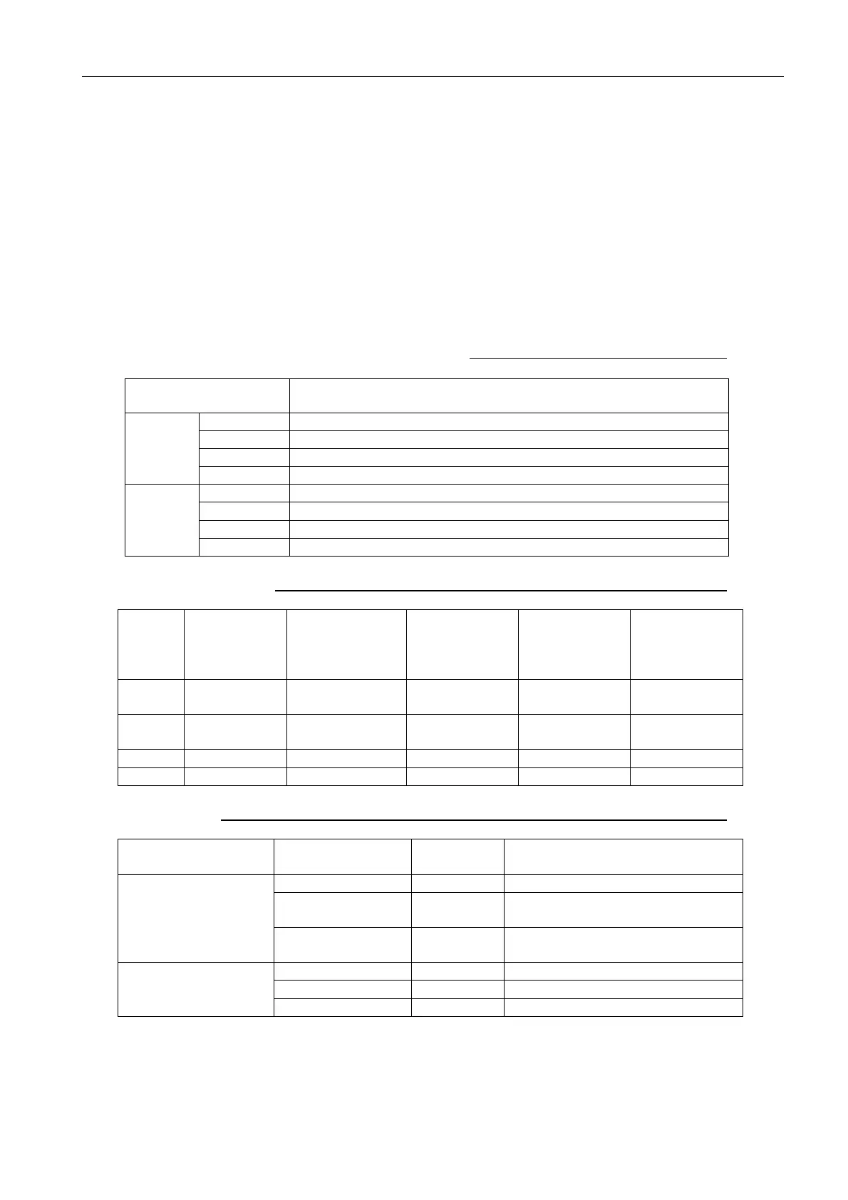
Table 7.3.5 Input protection operating voltage of power board
Type Power Board
F1:
Fuse capacity
Over voltage
protection
operating
voltage
Low voltage
protection
operating
voltage
Power supply
starting
voltage
100
VA C
03P9339A/B 10 A (125 VAC) 144 VAC 75 VAC 84 VAC
220
VA C
03P9339C/D 5 A (250 VAC) 288 VAC 159 V 181 VAC
24 VDC 03P9338A/B 20 A (125 VAC) 36 VDC 15 VDC 18.5 VDC
12 VDC 03P9338C/D 30 A (125 VAC) 36 VDC 8 VDC 9.8 VDC
Table 7.3.6 Over current protection operating current of power board
Protection Output line
Operating
current
Remarks
+24 VDC TX-HV 5 to 7 A With delay of 0.1 s
+24 VDC ANT
power supply
4 to 5 A With delay of 0.1 s
Output short-circuit
protection operating
current
ANT motor line 2.8/6.4 A
2.8 A or more: Turned of with a
delay of 2 to 3.5 s
+12 VDC 5.5 A
-12 VDC 0.54 A
Output over current
protection operating
current
+5 VDC 8.5 A

 Loading...
