6.5 Replacement of Major Parts
6-44
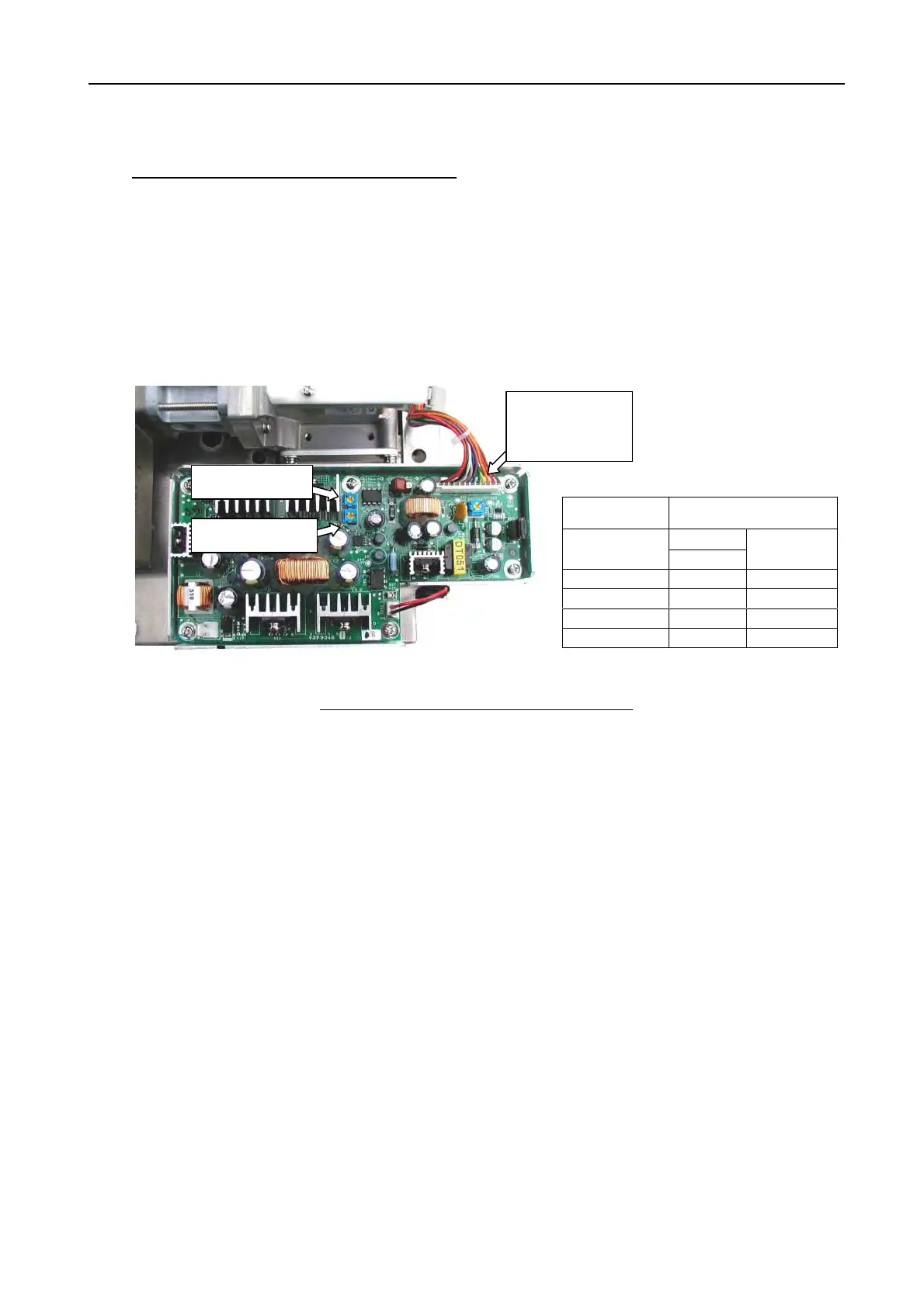
2) Method for adjusting the heater voltage
Basically, there is no need for adjusting the heater voltage in the field. The heater
voltage is measured at J833-#11 and-#12 on the PWR (RF) board.
- In ST-BY, S1-M1 pulse state:
Adjust R28 on the PWR (RF) board so as to achieve the voltage specified.
- In TX, M2-L pulse state:
Adjust R32 on the PWR (RF) board so as to achieve the voltage specified.
Fig. 6.5.2 Adjustment of the Heater Voltage
4. Replacement of MIC
If the MIC is damaged, the R. MONITOR values are substantially varied.
When replacing the MIC alone, it may be damaged if radar waves from other ship get
into it. When replacing the MIC, be sure to do replacing works in a room or a ship so
as to prevent radar waves from getting into the MIC.
After the replacement, be sure to execute “TUNE INITIALIZE”.
- Setting of “TUNE INITIALIZE: [Menu] -> 1 -> 3:TUNE INITIALIZE”
R28(Mag. H)
Checking of
heater voltage
(J833-#11-#12)
R32(Mag. L)
Model HEATER
Tx/L
FAR-2x17
STBY/S
7.4 to 7.6
FAR-2x27 Tx/L 6.5 to 7.5
FAR-2827W STBY/S 8.2 to 8.4
FAR-2x37S Tx/L 7.2 to 7.8
FAR-2x37SW STBY/S 9.1 to 9.3
 Loading...