4.14 Change of Transmission HV setting: HV-9017
4-70
4.14.1 Setup
Table 4.14.1 Setting of HV-9017
HV-9017
Jumper setting
Radar type
(TR unit)
Transmission
output
RPU-013
SER. NO.
Type
JP1 JP2
Adjustment Specification*
FAR-2x17
(RTR-078)
12 kW 4317-xxxx A COM-300V COM-330V 310 to 350 V
FAR-2x27
(RTR-079)
25 kW
FAR-2x37S
(RTR-080)
30 kW
FAR-2827W
(RTR-081)
25 kW
FAR-2837SW
(RTR-082)
30 kW
4318-xxxx B COM-500V COM-330V
Adjustment
of Main
Inverter
Adjustments on
the VR1 so that
34.7-35.3 VDC
is achieved
between
TP1 and TP2.
520 to 580 V
* As for the measurements, perform on the TB board: HV J651 and J482 on the HV-9017 board. Refer
to the previous page.
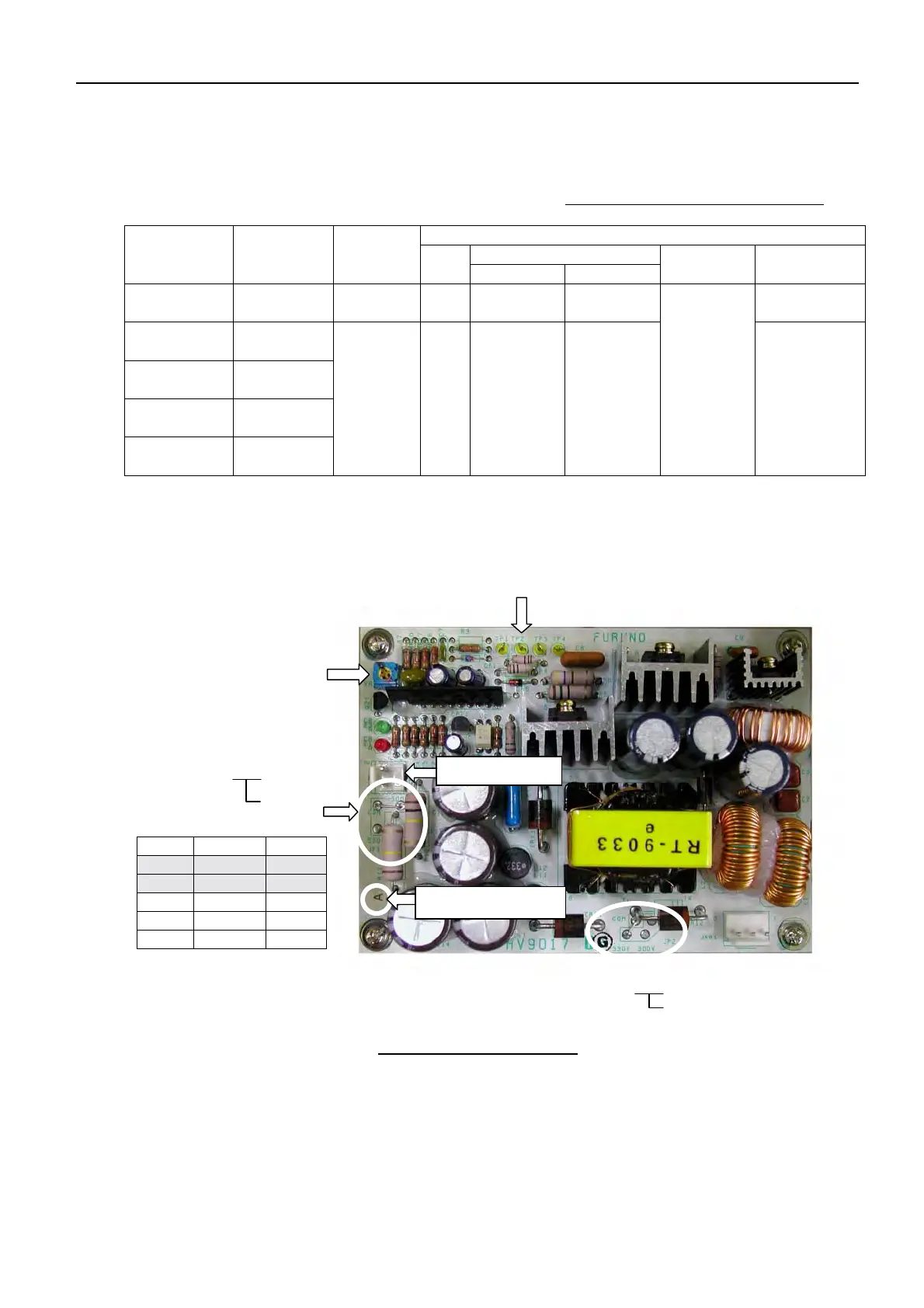
Fig. 4.14.3
HV-9017 Board
Type JP1 JP2
A 300 V 330 V
B 500 V 330 V
C 300 V 260 V
D 300 V 300 V
E 500 V 300 V
TP1 to TP4
VR1: Output voltage adjustment
Between TP1 and TP2
34.7 to 35.3 VDC
JP2
COM300 V
330 V
JP1
COM300 V
500 V
A/B type marking
J482: HV output
 Loading...