7.3 Processor Unit: RPU-013
7-69
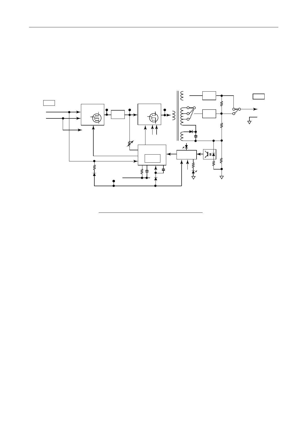
7.3.6 TX-HV board (HV-9017)
The setting of JP1 and JP2 on the TX-HV board differs depending on the radar TX
output of 10 kW and 25 kW or more. See page.4-69 for the related setting.
Fig. 7.3.27 Block diagram of TX-HV board
The TX-HV board is comprised of a main inverter and sub inverter. Each inverter is
controlled by U1 and the switching frequency is about 45 kHz and determined by R2, 3
and C7. U1 incorporates the IC for pulse length control of MB3757 with its peripheral
circuitry molded.
CR23 lights up when the power is supplied to this board and CR21 lights up when over
current of about 0.7 A is detected on the TX-HV. VR1 should be adjusted so that the
output voltage of the main inverter of TP-1 is 35 VDC. TX-HV voltage is set at JP1 and
JP2. The voltage setting is 310 to 350 VDC in case of a 10 kW –radar (FAR-2x17) and
520 to 580 VDC incase of radar of 25 kW or more (FAR-2x27).
0
160V
160V
260V
330V
300V
REC
(CR12)
300V
300V
500V
500V
REC
(CR11)
REC
(CR3)
JP1
CR21
CR23
JP2
1. Tx-HV
2. GND
U2
SW
(Q2:2SK1432)
SW
(Q1:2SK1420)
T1
SW CONT.
(U1:RC6220)
PMW
(MB3759)
Over current
DET
IN2
IN1
CT
DT
RT
C7
OC
C7
CR1
CR6
(RD10EB1)
R2/3
VR1
E1
E2
Vcc
CONT.
CONT.
TP3
(45kHz)
TP1
(+35V)
TP4
(45kHz)
TP2
1. +24V
2. -24V
-24V
-10V
-10V
-10V
-24V
-24V
+24V
MAIN INV SUB INB
J481
J482
CR21(Red):Over Current
CR23(Green): Power IND
 Loading...