4.11 Alarm Output Setting
4-59
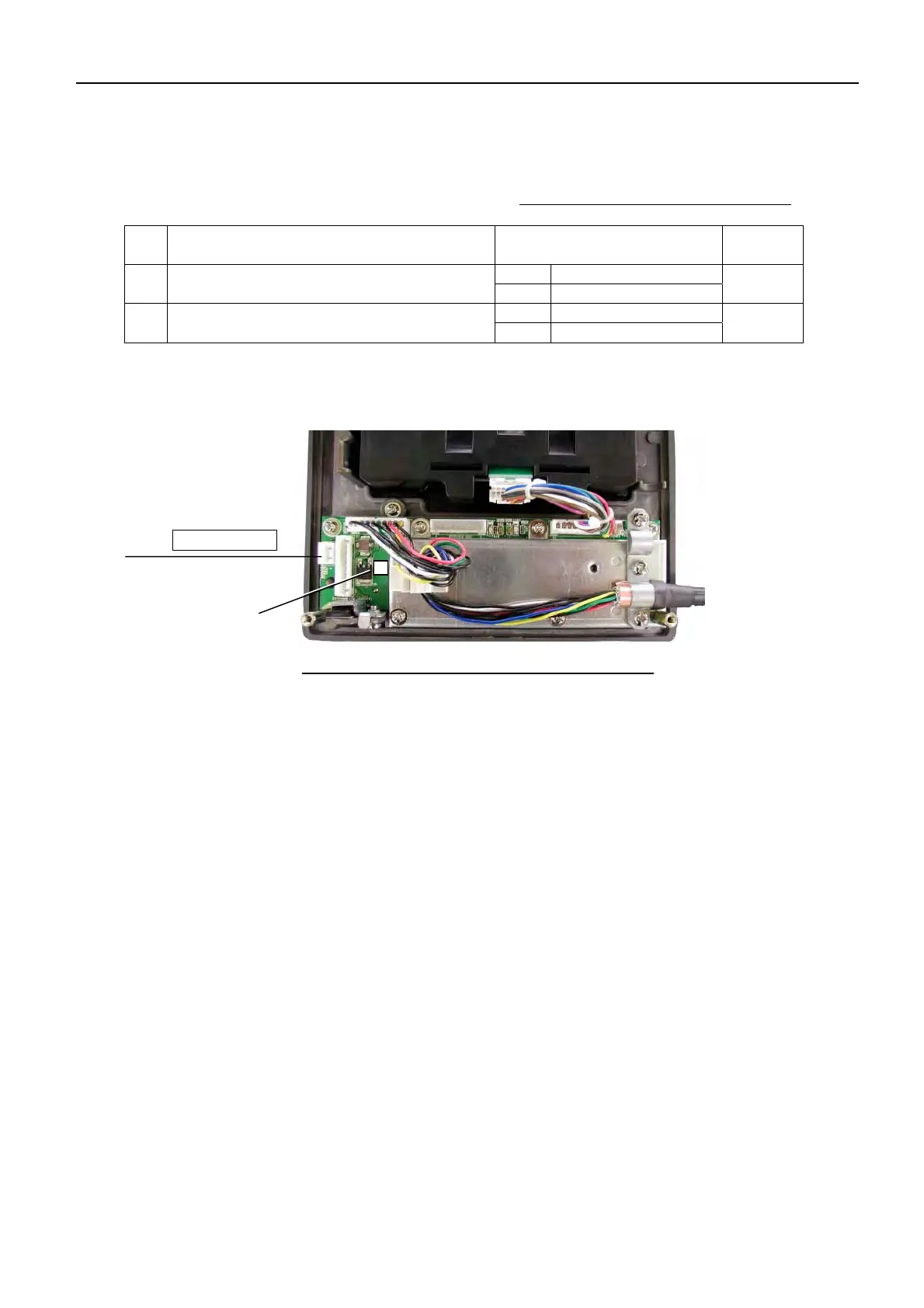
2. RCU-015 and 016
Table 4.11.2 Setting of RCU-014:S6
S6 Function Setting
Factory
Setting
ON Output
1
SYSTEM FAIL ALARM
The same as described for RCU-014
OFF Do not output
ON
ON Normally Close
2
RELAY STATUS
The same as as described for RCU-014
OFF Normally Open
ON
Fig. 4.11.2 Location of S6 on RCU-015 and 16
3. Operation of SYSTEM FAIL ALARM
SYSTEM FAIL ALARM is outputted from the control unit (RCU-014) side. The control
unit regularly sends check signals to the processor unit (RPU-013). When there is no
response from the processor unit, the control unit judges as a communication error and
outputs “SYSTEM FAIL”. At this time, continuous beeps keep sounding and the LED of the
[ALARM ACK] key keeps blinking on the control unit. When there is a response of
“SYSTEM ALARM ACK” on the control unit keep blinking, from the alarm system side or
[ALARM ACK] key is pressed, beeping sounds on the control unit stops and the LED of
[ALARM ACK] key lights on. The I/O terminals of control unit are the same as those of
RCU-015.
Note:
When the communication with processor unit is disabled due to the problem on the control
unit side, “KEY” alarm is displayed in the ALARM box and the control unit gives beeping
sounds. The control unit does not output SYSTEM FAIL ALARM.
S6 (DIP SW)
J527: SYSTEM FAIL
 Loading...