7.2 Antenna Unit
7-13
7.2.3 IF board (03P9335)
The IF board has different parts in X-band and S-band radars and is not compatibly used
for different types of radars.
03P9335A 03P9335B
IF board for X-band radar IF board for S-band radar
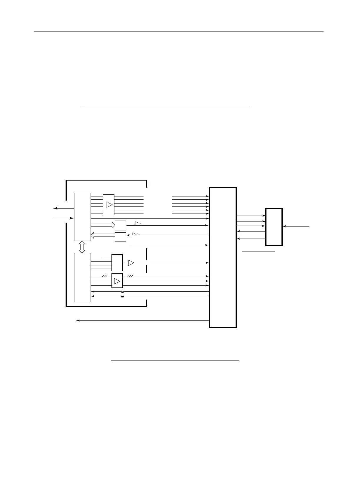
The IF board is comprised of a video detection circuit and the semi-log amplifier circuit
of IF signals (60 MHz). IF signals of 60 MHz and video signals are superimposed and
outputted from the IF board to the Processor unit. Video signals are outputted to allow
connection to an existing type of a sub monitor.
Fig. 7.2.8 Connection of RFC board IF board
STC DETECT
TUNNING
+12V / +5V / -12V
STC-CONT
TUNE
PIN ATT*
+5V*
IF(60MHz)
DI-MONITOR
TUNE SYNC
TUNE SCLK
TUNE DIN
SDATA/CLK/DATAE
VBW A/B
TUNE GAIN
D MONI AD
TUNE AD
D MONI
TUNE IDN
TEST SIG
TX data
RX data
2.5V
U11
U13
(D/A)
Data D0-7
U16
(D/A)
U10
Data D0-7
U7
(A/D)
IF
(03P9335)
MIC
U12, 1
RFC (03P9346A)
U17
(FPGA)
U19
(CPU)
MIX Sig.
IF SIG.(60MHz)
and
Video SIG.
X/S band Echo
PIN ATT CONT
FET ATT
TUNE GATE
SAMPL HOLD
MSB ENABLE
TEST SIG ENABL
X band* S band*
PIN ATT none
+5V +9V
 Loading...