AP1.1 Overview of NMEA-0183 Ver-3.00
AP1-1
AP1.1 OVERVIEW of NMEA-0183 Ver-3.00
1.1.1 Overview of connection
1. Connection
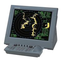
Multiple LISTENER may be connected to single TALKER. The LISTENER receive
circuit shall consist of an opto-isolator and should have protective circuits to limit
current, reverse bias and power dissipation at the opto-diode as shown in Figure 1.1.1
The receive circuit shall be designed for operation with a minimum differential input
voltage of 2.0 Volts and shall not take more than 2.0 mA from the line at that voltage.
For reasons of the compatibility with equipment designed to earlier versions of this
standard, it is noted that the “idle, marking, logical “1”, OFF or stop bit state” had
previously been defined to be in the range –15 to +0.5 Volts. The “active, spacing,
logical “0”, ON or start bit state” was defined to be in the range +4.0 to +15 Volts while
sourcing not less than 15 mA.
Fig. 1.1.1 Overview of Connection
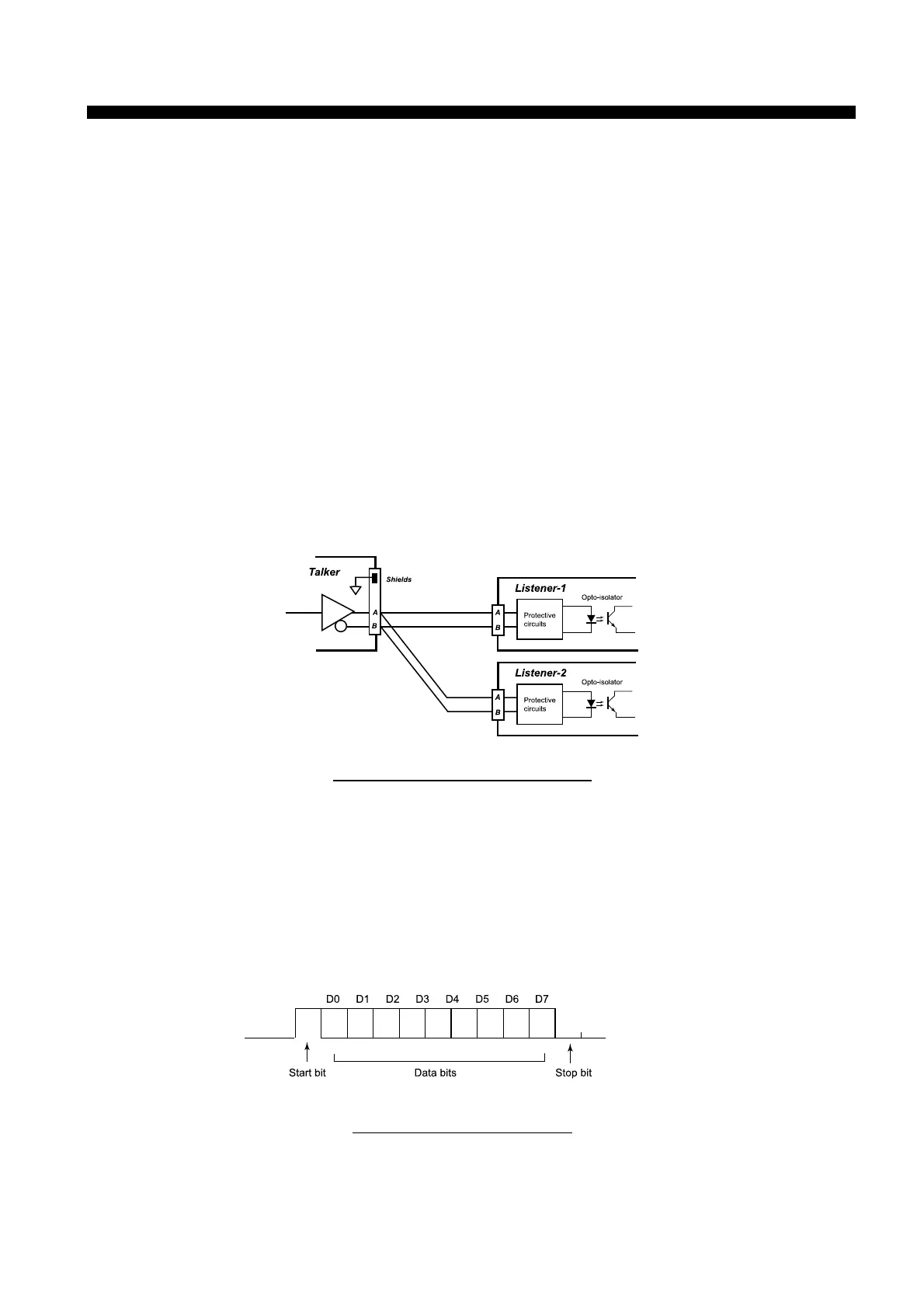
2. Data configuration
Data is transmitted in serial asynchronous form in accordance with ANSI standards. The
first bit is a start bit and is followed by data bits, least-significant-bit first as illustrated
by Figure 1.1.2. The following parameters are used:
- Baud rate 4800 - Data bits 8 (d7=0)
- Parity None - Stop bits One
Fig. 1.1.2 Data Configuration
Appendix 1) Sentences
Appendix 1) SentencesAppendix 1) Sentences
Appendix 1) Sentences
 Loading...