7.2 Antenna Unit
7-16
- FET ATT N
This is a control signal for adjusting the ring suppression. When the control time of
the MBS is complete, this signal starts to reduce the gain of Q1 to activate the ring
suppression. The larger is the setting value of [Menu] -> 0 -> 2 -> 0:Ring
Suppression, the more extended is the time for enabling the ring suppression.
- STC CONT
This is the STC control signal to control the gain of U27 and 28.
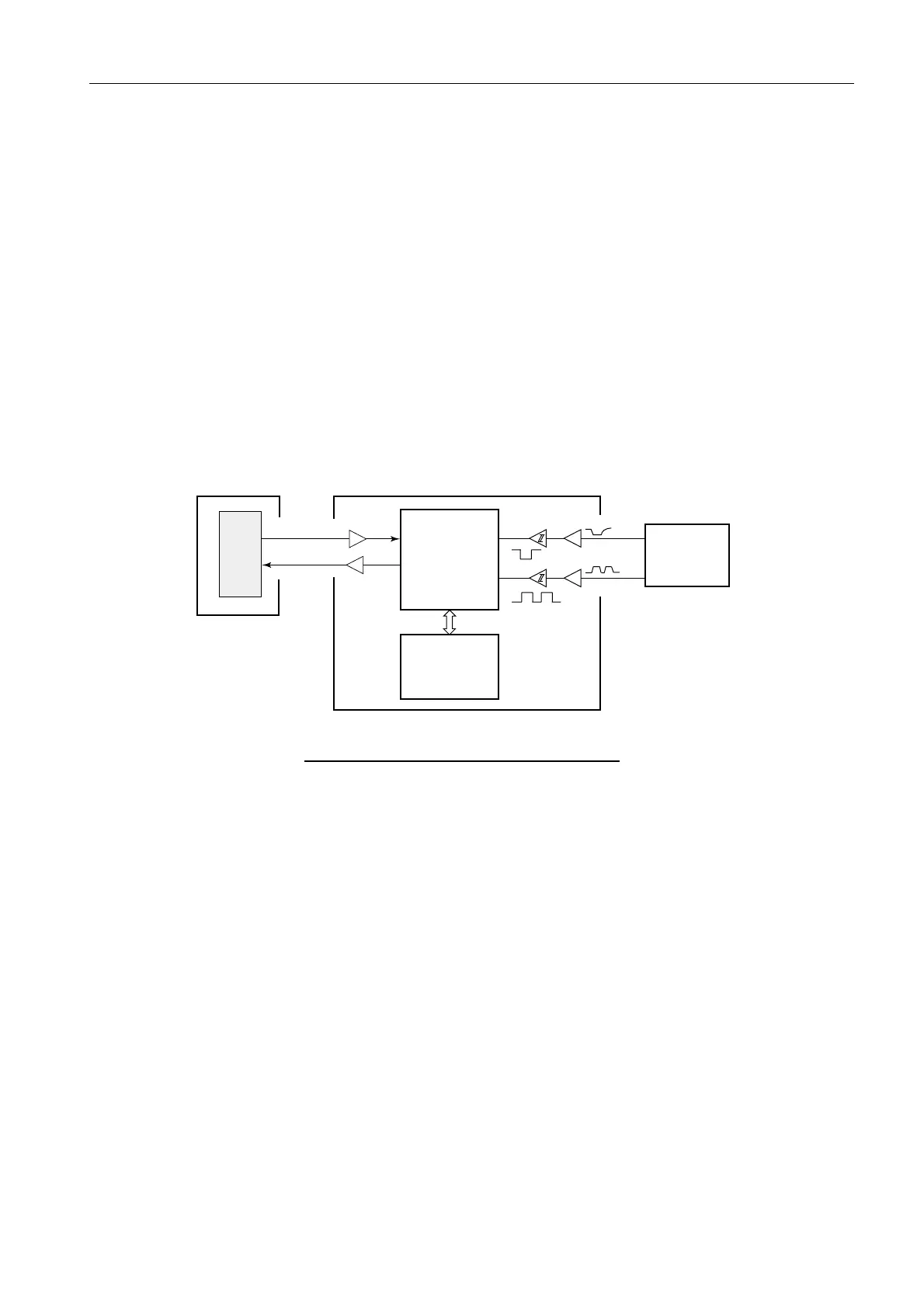
7.2.4 B.P GEN board (03P9347)
The B.P GEN board is commonly used for different types of radars. B.P (Bearing Pulse)
and HD (Head line) signals are sent as serial data from the RFC board to RPU-013.
Fig. 7.2.10 Connection of B.P GEN board
1. B.P signal
B.P signals are created by passing the slits of timing disk through the photo-interrupter
on the B.P GEN board. The timing disk is mounted on the rotary joint shaft in case of
the S-band radar and on the drive gear shaft in case of the X-band radar. The number of
pulses generated from the B.P GEN board is 256 pulses/rev of the antenna on the
S-band radar and 360 pulses on the X-band radar. B.P signals outputted to Slave-1 and
Slave-2 are converted at SPU FPGA on the SPU board and outputted at 360 pulses both
on X-band and S-band radars. See page.4-68 and 4-76 for related information.
U15
U15
RF RX data
RF TX data
HD
BP
U19
(RFC CPU)
U17
(FPGA)
U14
U14
U30
U30
SPU
BP GEN
(03P9347)
RFC (03P9346A)
RPU-013
 Loading...