7.5 Monitor Unit
7-75
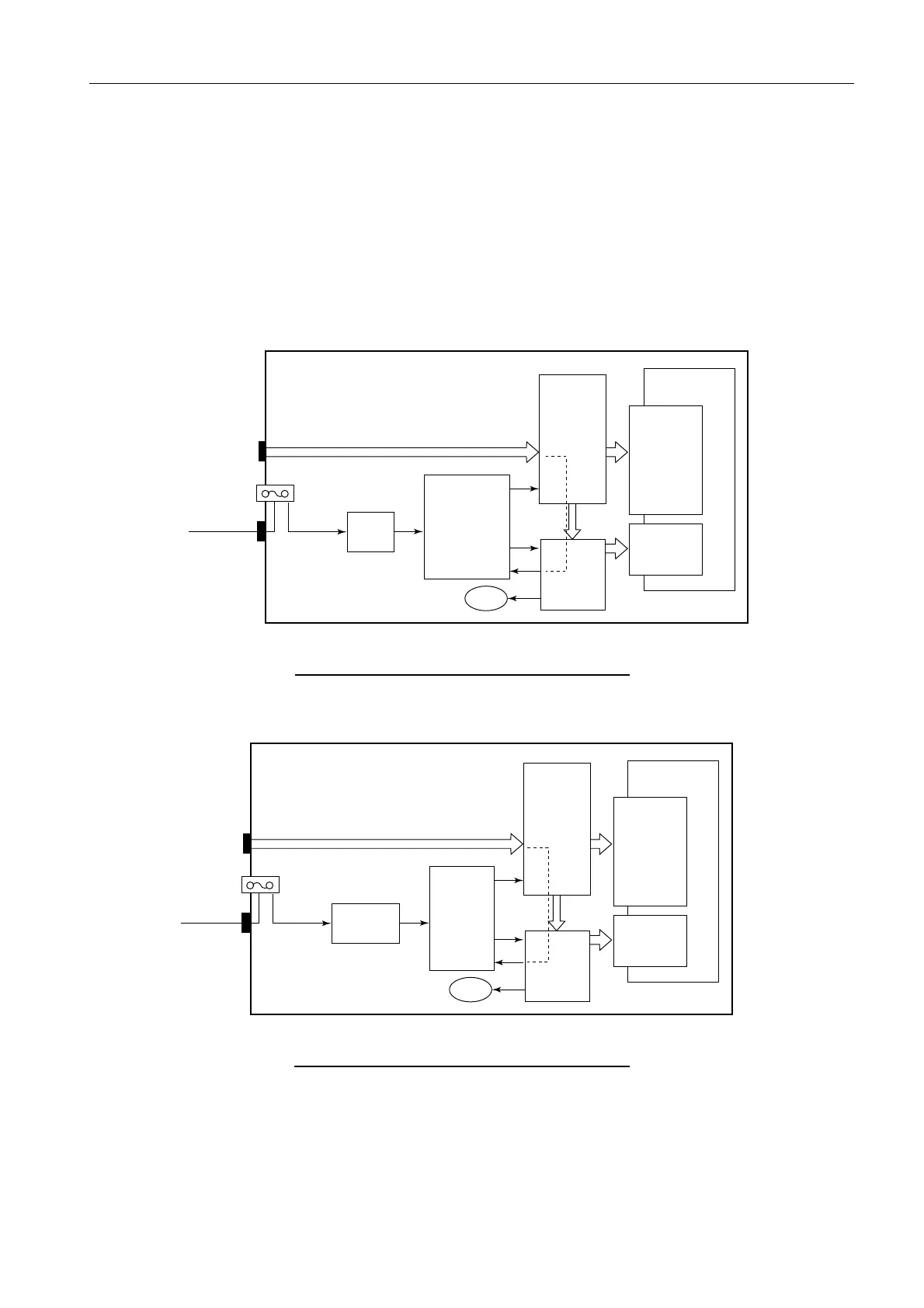
2. MU-231CR
The power-on signal of the monitor unit is inputted into the DVI I/F board as signals of
#14 pin (+5 V POWER) of the DVI connecter. The DVI I/F board outputs DDC +5 V
signals based on these signals to control ON/OFF of the power supply unit and outputs
“RC+/-” signals via the filter board. The DVI I/F board also converts SXGA signals into
UXGA signals.
Fig. 7.5.3 Block diagram of MU-231CR (AC)
Fig. 7.5.4 Block diagram of MU-231CR (DC)
AC/DC power
(RKW12-13RE-P)
FL1
(LF 205A)
Ship’s Main
DVI
(SXGA)
LCD panal
FLC59UXC8V-04
LCD I/F Board
Inverter Board
Filter Board
(03P9360)
DVI I/F Board
(BSM501FN1)
+12V
+12V
+24V
RC+
RC-
Power ON +5V
Data/CLOCK
100-240VAC
F1: 2A
TB1
VVR
VCNT
FAN
DVI SXGA -->
LVDS UXGA
Power ON +5V
DDC+5V
DC/DC Board
(03P9359)
FL1
(MXB-1206-33)
Ship’s Main
DVI
(SXGA)
LCD panal
FLC59UXC8V-04
LCD I/F Board
Inverter Board
Filter Board
(03P9360)
DVI I/F Board
(BSM501FN1)
+12V
+12V
+24V
RC+
RC-
Power ON +5V
Data/CLOCK
24VDC
F1: 6A
TB1
VVR
VCNT
FAN
DVI SXGA -->
LVDS UXGA
Power ON +5V
DDC+5V
 Loading...