om 5184516-100 Rev. 5 9-8
ILLUSTRATION 9-5
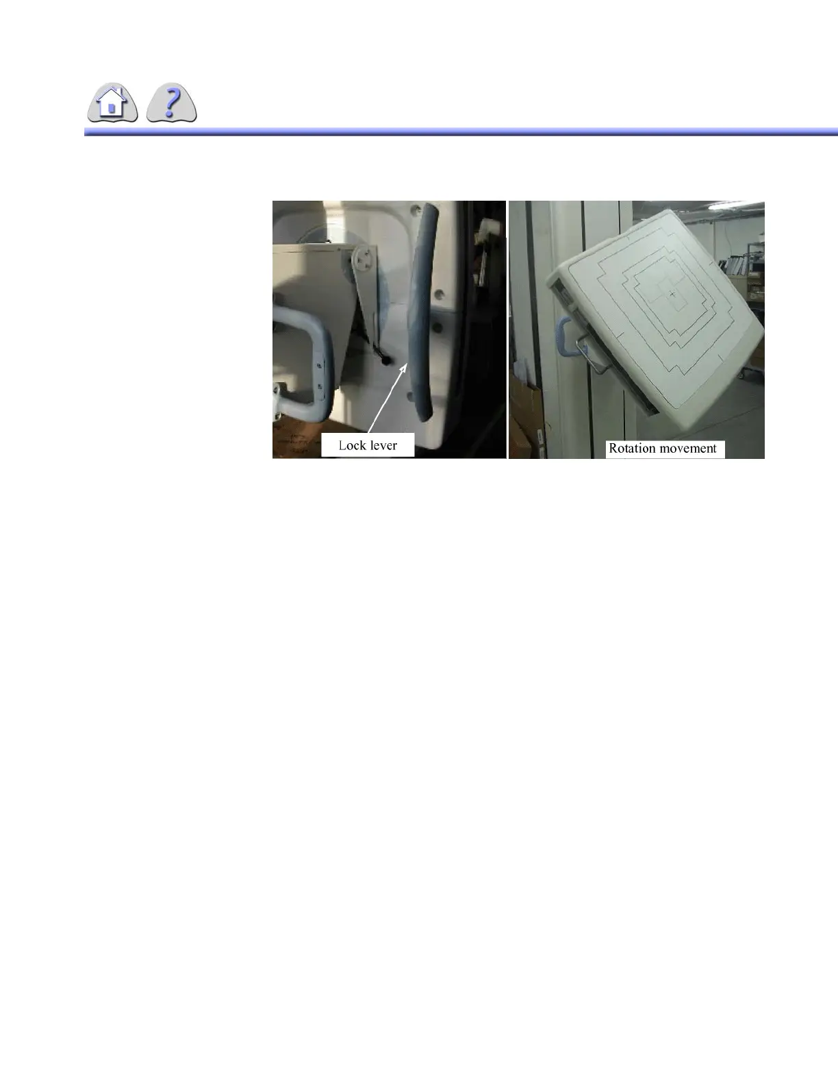
Bucky Rotation
Procedure: See ILLUSTRATION 9-5
1. 1. Release the lock lever .
2. 2. Rotate the bucky to position
3. 3. Put the lock lever back into locked position.
NOTE: The bucky can be rotated CW (clockwise) or CCW (counter-clockwise). To avoid
degradation of image quality and loss of bucky functionality, it is recommended
not to perform exposures with the bucky in other position than 0 degrees or 180
degrees. The bucky is designed to operate only at 0 degree or 180 degree posi-
tions, but will function in a range within 30 degrees of these positions. The image
quality may be degraded, however.
4-7-2 Bucky Angulation
The SG120 bucky assembly can be angulated in a range that varies from -20
degrees to 90 degrees. The bucky in locked means of the electro-mechanical
detents located in the bucky support assembly. The angulation movement is left
free when activating one of the pushbuttons located behind the bucky support.
FOR TRAINING PURPOSES ONLY!
NOTE: Once downloaded, this document is UNCONTROLLED, and therefore may not be the latest revision. Always confirm revision status against a validated source (ie CDL).

 Loading...


