5-16 VersaMax® Modules, Power Supplies, and Carriers User's Manual – February 2003 GFK-1504K
5
IC200CHS111, Main Base
IC200CHS112, Expansion Base
Relay-Style Interposing I/O Terminals
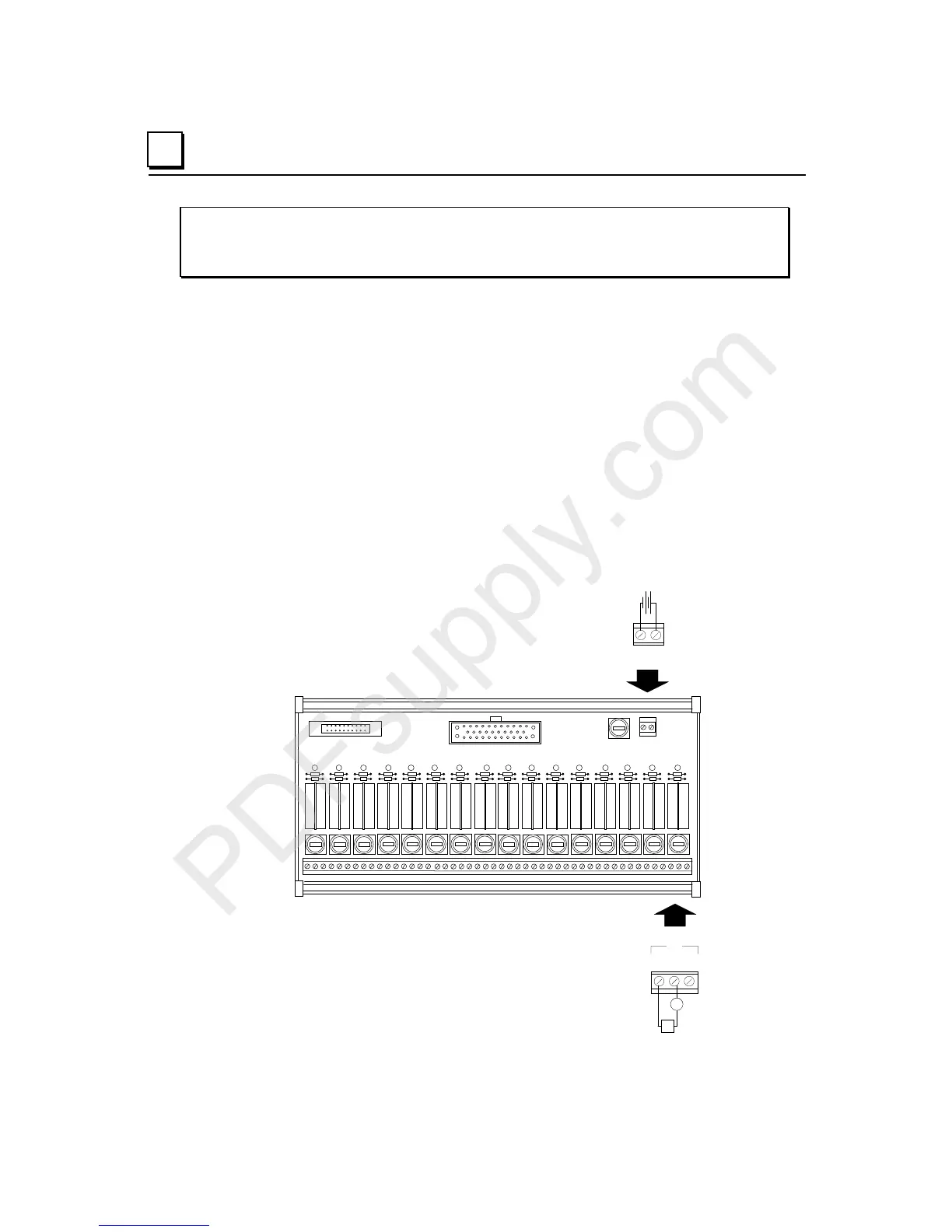
Field Wiring
Power for operation of the relay coils must be provided by an external 24VDC power
supply. This power must be provided to both the main base and the expansion base.
Connection of this external power supply is made at the terminals A17 & A18 (B17 & B18
for the expansion base). This power connection is for the relay coils only. User loads
must be powered by an external source.
Each relay, status LED and fuse is labeled to indicate the specific point on the VersaMax
output module they are associated with. Components labeled A1-A16 correspond to
points Q1-Q16. Components labeled B1-B16 correspond to points Q17-Q32. Each point
is associated with 3 terminal connections, labeled NO (Normally Open), C (Common), and
NC (Normally Closed). User loads may be connected between C and NO, C and NC, or
both.
J1
J2
A16 A15 A14 A13 A8 A7 A6 A5 A4 A3 A2 A1A12 A11 A10 A9
A16 A15 A14 A13 A8 A7 A6 A5 A4 A3 A2 A1A12 A11 A10 A9
A17A18
-
+
24VDC
A1
V
Q1
NO C NC

 Loading...


