11-10 VersaMax® Modules, Power Supplies, and Carriers User's Manual – March 2003 GFK-1504K
11
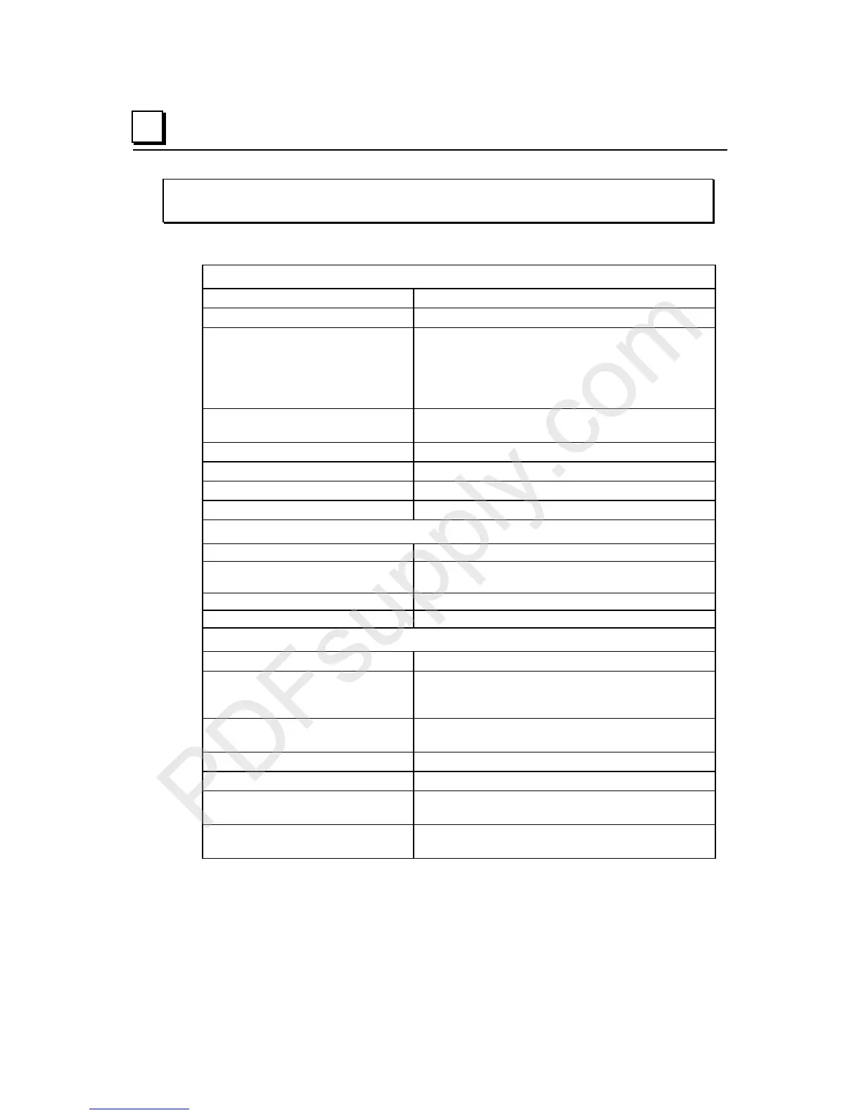
IC200ALG321
Analog Output Module, 12 Bit Voltage 0 to 10VDC 4 Channels
Module Specifications
Module Characteristics
Channels 4 single-ended, one group
Module ID FFFF9040
Isolation:
User input to logic (optical) and
to frame ground
Group to group
Channel to channel
250VAC continuous; 1500VAC for 1 minute
Not applicable
None
LED indicators FLD PWR LED indicates field power is present
OK LED indicates backplane power is present
Backplane current consumption 5V output: 50mA maximum
Thermal derating None
Configuration parameters Output default
Diagnostics Loss of User Side Power
External Power Supply
Recommended range +18 to +30VDC (including ripple)
Current consumption at
recommended range
160mA max.(including load current)
12V operation range 9.6 to 15VDC, 12VDC nominal (including ripple)
Current consumption at 12V range 210mA max.(including load current)
Output Characteristics
Output voltage 0 to 10.24VDC
Load characteristics:
Resistive
Capacitive
5000 Ohms minimum
1.0µF maximum
Accuracy at 25 degrees C*
Accuracy at 0 to 60 degrees C
+/- 0.3% typ. of full scale, +/- 0.5% max. of full scale
+/-1% maximum of full scale
Resolution 2.5mV = 8 counts
Update rate per module 0.3ms maximum
Channel-to-channel crosstalk
rejection
70dB minimum
Output default Hold Last State (default)
0 (configurable)
* In the presence of severe RF interference, (IEC 1000-4-3, 10V/m), accuracy may be
degraded to +/-1%.

 Loading...


