2-30 VersaMax® Modules, Power Supplies, and Carriers User's Manual – March 2003 GFK-1504K
2
Disconnect-Style Interposing I/O Terminals,
Wiring for Modules with Connections that are Not Grouped
This wiring format generally applies when the associated VersaMax module provides for
connection of isolated I/O devices, but may also be used when a non-isolated module
provides dedicated terminals for each common connection. An example of an isolated
module is the VersaMax 120VAC 8pt Isolated Input Module, IC200MDL143:
I1 I2 I3 I4 I5 I6 I7 I8
12345678
9
11 12 13 14 15 16 17 1810
A
NN N NNN N N
When connecting the Interposing Disconnect bases in this format, additional jumpers are
usually not needed. Field wiring is connected to terminals A1-A16 (or B1-B16 where
appropriate). The auxiliary terminals are not generally connected.
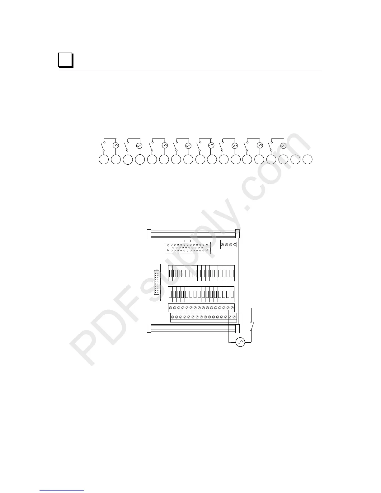
Example Wiring Diagram for Module IC200MDL143
Example field wiring for IC200CHS101 when used with VersaMax modules without
grouped points.
J1
J2
I1
A16 A1 5 A14 A1 3 A12 A11 A10 A9 A8 A7 A6 A5 A4 A3 A2 A1
X8 X7 X6 X5 X4 X3 X2 X1 W8 W7 W6 W5 W4 W3 W2 W1
A18 A17 X W

 Loading...


