7-6 VersaMax® Modules, Power Supplies, and Carriers User's Manual – March 2003 GFK-1504K
7
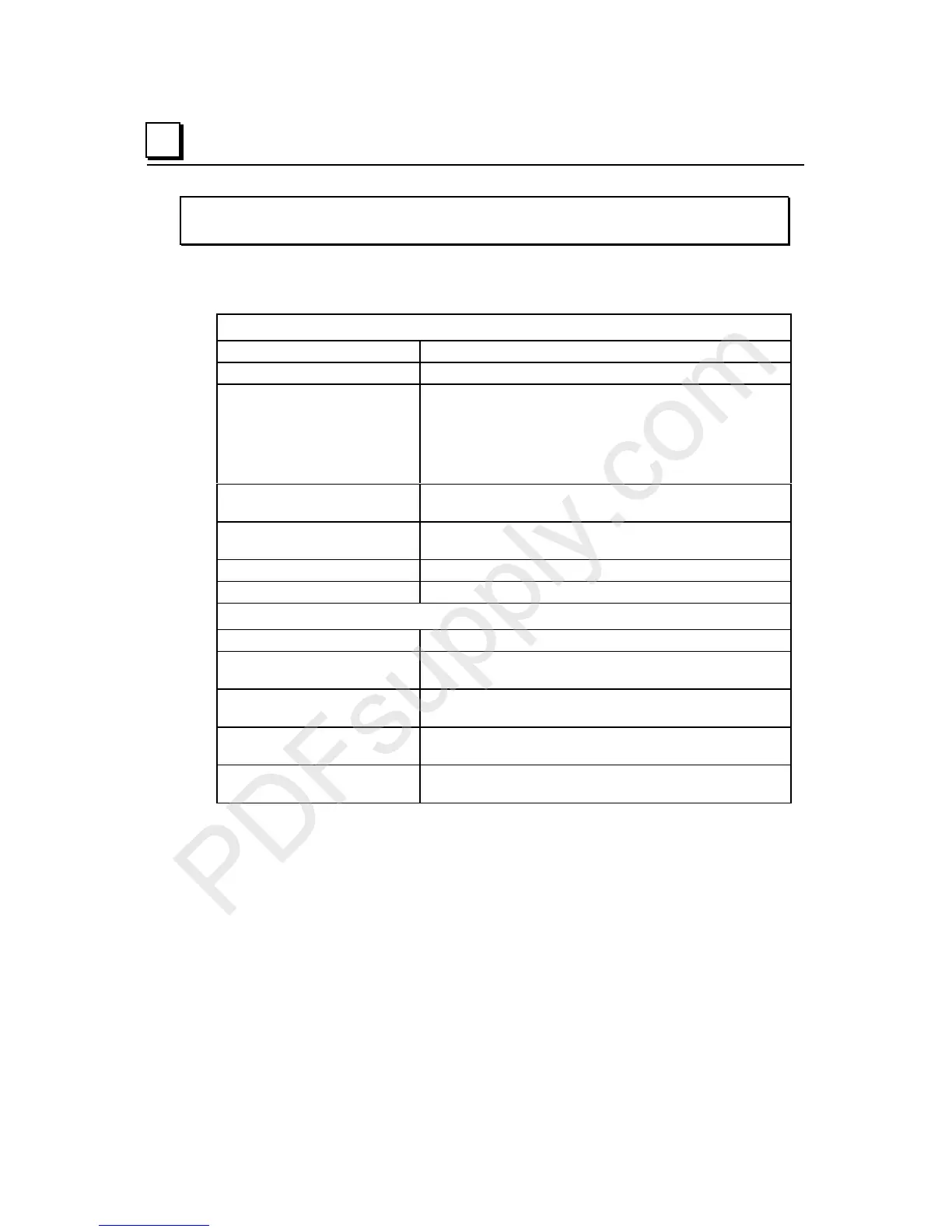
IC200MDL141
Input Module, 240VAC 8 Points
Module Specifications
Module Characteristics
Points 1 group of 8 inputs
Module ID FFFF8804
Isolation:
User input to logic (optical)
and frame ground
Group to group
Point to point
250VAC continuous; 1500VAC for 1 minute
Not applicable
None
LED indicators One LED per point shows individual point ON/OFF status
OK LED indicates backplane power is present
Backplane current
consumption
5V output: 55mA maximum
External power supply None
Thermal derating None
Input Characteristics
Input voltage 0 to 264VAC (47 to 63Hz), 240VAC nominal
On state voltage
Off state voltage
155 to 264VAC
0 to 40VAC
On state current
Off state current
7mA minimum
1.5mA maximum
On response time
Off response time
1 cycle maximum
2 cycles maximum
Input impedance 38.5kOhms (reactive) at 60Hz, typical
46.3kOhms (reactive) at 50Hz, typical

 Loading...


