GFK-1504K Chapter 2 Installation Instructions 2-33
2
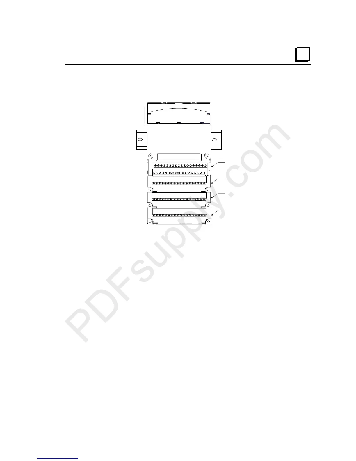
For example, a 16-point module might use 3 Auxiliary I/O Terminals for 4-wire devices:
Point Connections
Common Connections
+V Connections
-V Connections
Auxiliary I/O Terminals accommodate current levels up to 8 Amps and voltage up to 264
VAC. Voltage transients up to 300 VAC will not cause damage.
Installing Auxiliary I/O Terminals
Auxiliary I/O Terminals are installed by inserting the tabs into the slots on the I/O Carrier
or Interposing Terminals and pressing downward. Screws can be inserted through the
panel-mount holes for added stability if needed.
Auxiliary Carriers must be installed on the I/O Carrier or Interposing Terminals before
connecting field wiring.
Wire Specifications for Auxiliary I/O Terminals
Wire specifications depend on the terminal type. For box-type or spring type terminals, each
terminal accommodates one solid or stranded AWG #14 (avg. 2.1mm
2
cross section) to
AWG #22 (avg. 0.36mm
2
cross section) wire, or two wires up to AWG #18 (avg. 0.86mm
2
cross section).
For barrier-type terminals, each terminal accommodates one or two solid or stranded wires
from AWG #22 (avg. 0.36mm
2
cross section) to AWG #14 (avg. 2.1mm
2
cross section).
Use copper wire rated for 90 degrees C. When inserting two wires in the same position, the
wires must be the same size and type (solid or stranded).

 Loading...


