GFK-1504K Chapter 2 Installation Instructions 2-21
2
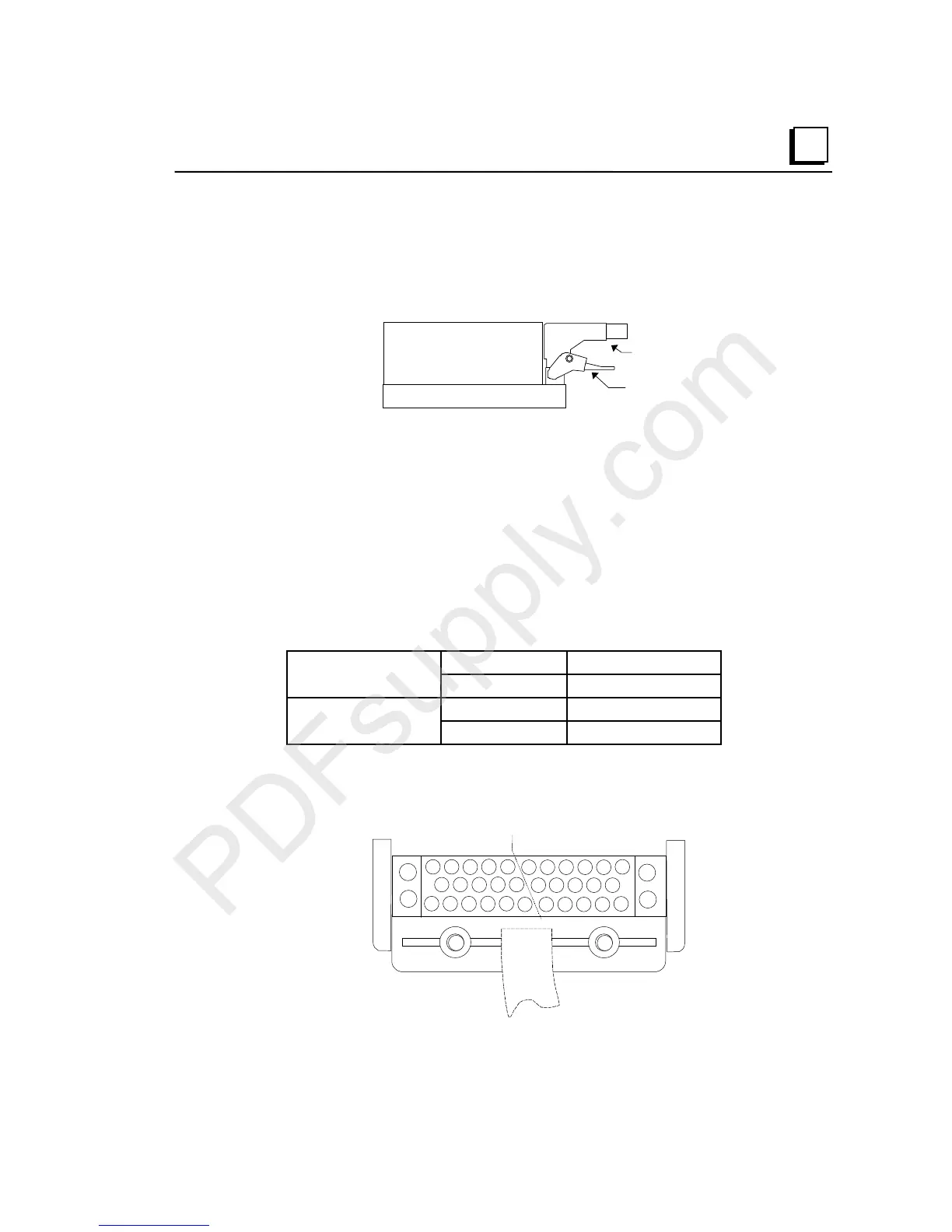
Installing and Removing a Prewired Cable
To install a prewired connecting cable, place the cable connector over the connector on the
carrier and press downward until the latch engages the tab on the connector. (If you have
an IC200CBLxxx cable with a non-molded style connector, please turn to appendix E for
installation and removal instructions).
Latch
Cable
To remove the cable, hold the cable connector and press up on the latch to release the
connector. When removing the cable, remember that operating equipment may be very hot,
especially at higher ambient temperatures. If the equipment is hot, do not touch it directly.
DO NOT TOUCH exposed connector pins if the system is operating.
Connector Kit
A connector kit (part number IC200ACC304) is available for building custom cables or for
connecting wires directly from field devices. The kit includes a connector and cover, two
screws, 36 small contacts, and 6 large contacts. The following equipment is also required
but not included in the kit:
Crimping Tools small contact Molex 11-01-0008
large contact Molex 11-01-0084
Extraction Tools small contact Molex 11-03-0002
large contact Molex 11-03-0006
Terminal Numbering
The illustration below shows the terminal assignments of the connector pins as viewed
from above.
A1 A2 A3
A4
A5
B5 B6 B3 B4 B1 B2
A6 A7 A8
A9
A10 B12 B9 B10 B7 B8
A11 A12 A13
A14
A15 A16 B15 B16 B13 B14 B11
B17
B18
A17
A18
B terminals
A terminals
Cable

 Loading...


