GFK-1504K Chapter 6 Expansion Modules 6-15
6
IC200ERM002
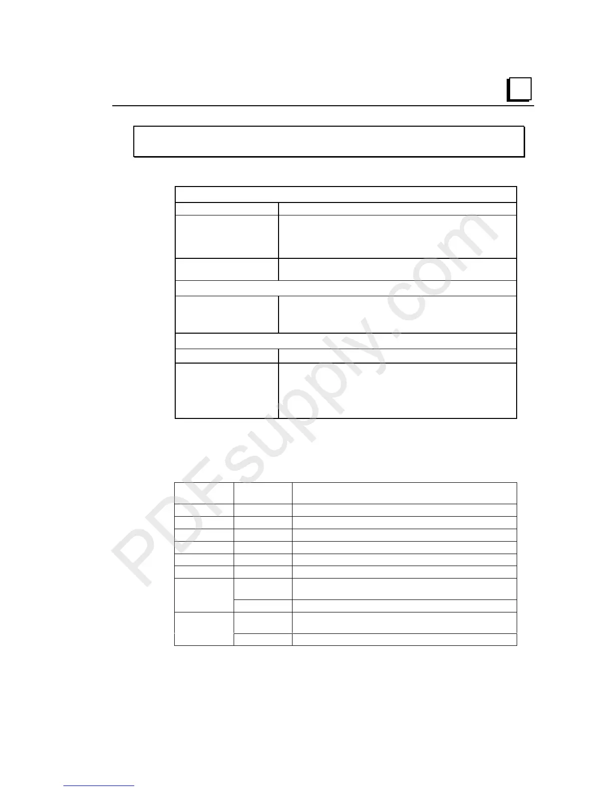
Expansion Receiver Module, Non-isolated
Module Specifications
Module Characteristics
Module ID
LED indicators PWR LED indicates 5VDC power status
EXP RX LED indicates expansion bus communications status
SCAN LED indicates whether the CPU/NIU is scanning I/O in
expansion racks
Backplane current
consumption
5V output: 70mA maximum
3.3V output: 20mA
Cable Specifications
Maximum cable length
Effective data rate
Electrical Isolation
15 meters (differential) . 1 meter (differential)
5 Mbits/sec (differential). 2.765 Mbits/sec (single-ended)
Non-isolated differential or single-ended communications
Catalog Numbers
Bus Receiver Module IC200ERM002
Expansion Cable
Terminator Plug
Connector Kit
IC200CBL601 - 1 meter
IC200CBL602 - 2 meters
IC200CBL615 - 15 meters
IC200ACC201 (included with ETM)
IC200ACC202
Compatibility
All I/O and communications modules can be used in expansion racks. Some analog
modules require specific module revisions as listed below. The date code is a 3-digit
number on the outside of the module and on the shipping box.
Module Module
Revision
Module Date Code Range
IC200ALG320 B or later Any
IC200ALG321 B or later Any
IC200ALG322 B or later Any
IC200ALG430 C or later Any
IC200ALG431 C or later Any
IC200ALG432 B or later Any
A or later
CPU or NIU Revision 1.5:
Date code must begin with a
number other than 9 and must be 011 or greater.
IC200ALG230
Any
CPU or NIU Revision 2.0 or later:
Any date code.
A or later
CPU or NIU Revision 1.5:
Date code must begin with a
number other than 9 and must be 011 or greater.
IC200ALG260
Any
CPU or NIU Revision 2.0 or later:
Any date code.

 Loading...


