2-26 VersaMax® Modules, Power Supplies, and Carriers User's Manual – March 2003 GFK-1504K
2
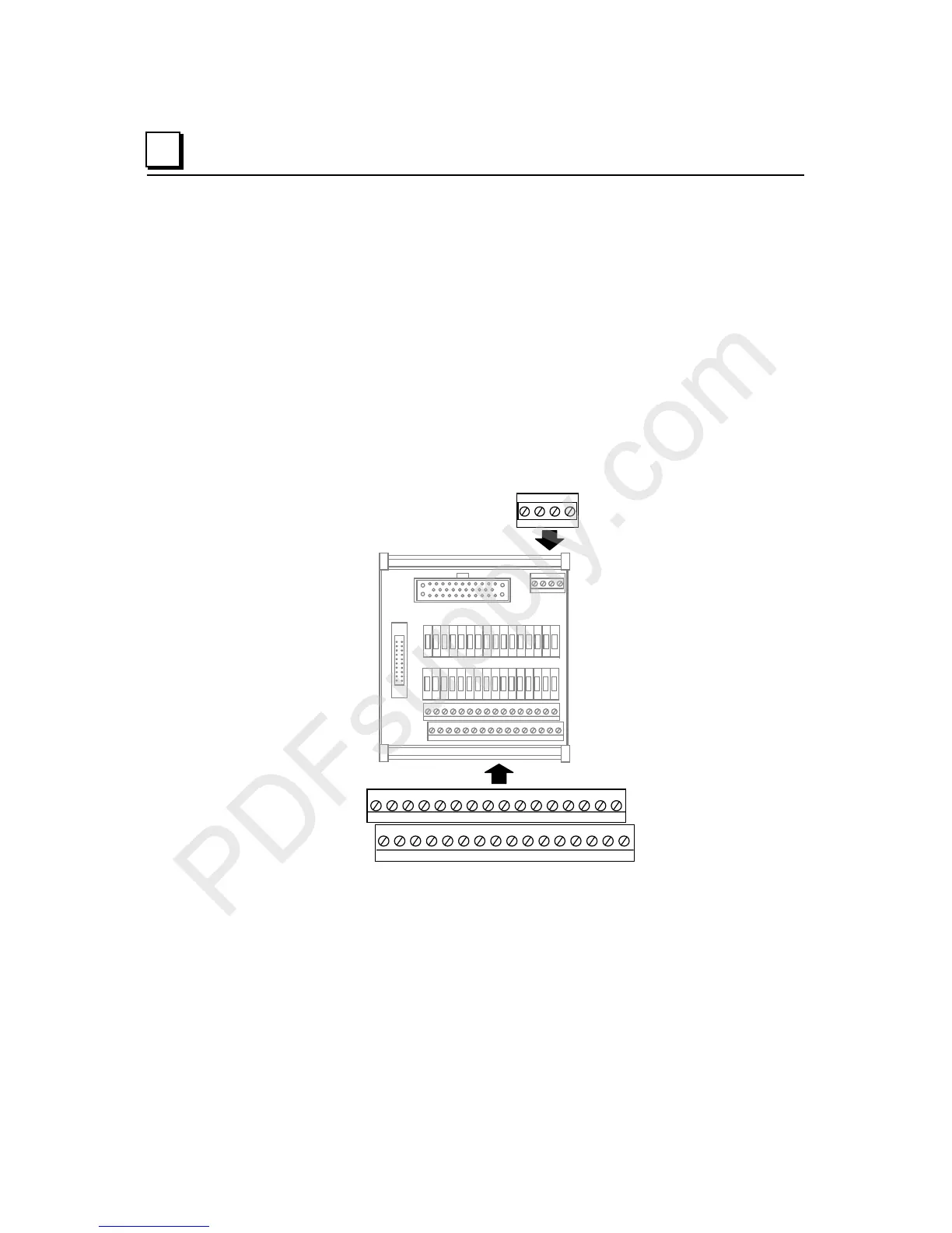
Installing Disconnect-Style Interposing I/O Terminals
IC200CHS101, IC200CHS102
The Disconnect-Style Interposing I/O Terminals (IC200CHS101 and IC200CHS102)
interface a VersaMax Connector-Style I/O Carrier to field wiring and provide an integrated
disconnect option for field devices connected to VersaMax I/O modules. The Main Base,
IC200CHS101, provides terminals that correspond to the "A" terminals on a VersaMax
I/O module. If the I/O module also has "B" terminals, an Expansion Base, IC200CHS102)
is also needed.
Field wiring to the interposing disconnect bases follows the standard wiring diagram for
each module. Terminals A1-A18 and B1-B18 on the interposing disconnect terminal
bases are connected in the same fashion as all other bases. The built-in auxiliary terminals
(W1-W8, X1-X8, Y1-Y8, Z1-Z8) are positioned directly below the A or B terminals to
provide for simple two-wire connection of field devices.
A16 A15 A14 A13 A12 A11 A10 A9 A8 A7 A6 A5 A4 A3 A2 A1
X8 X7 X6 X5 X4 X3 X2 X1 W8 W 7 W6 W 5 W4 W 3 W2 W1
A18 A17 X W
Each group of auxiliary terminals has a dedicated terminal to jumper the group to the
appropriate VersaMax terminal (The “W” terminal is the connection point for W1-W8,
etc.). The installation of these jumpers depends on the grouping present on the I/O
module, as shown on the following pages.

 Loading...


