GFK-1504K Chapter 2 Installation Instructions 2-29
2
Disconnect-Style Interposing I/O Terminals,
Wiring for Modules with Two Groups per Row
This wiring format generally applies when the associated VersaMax module provides for
connection of I/O in 8-point groups. An example of such a module is the VersaMax
24VDC 16pt Input Module, IC200MDL640:
1 2 3 4 5 6 7 8 9 11 12 13 14 15 16 17 1810
I1 I2 I3 I4 I5 I6 I7 I8 I9 I10 11 I12 I13 I14 I15 I16
A
+
-
(+)
(-)
+
-
(+)(-)
-
(+)
-
(+)
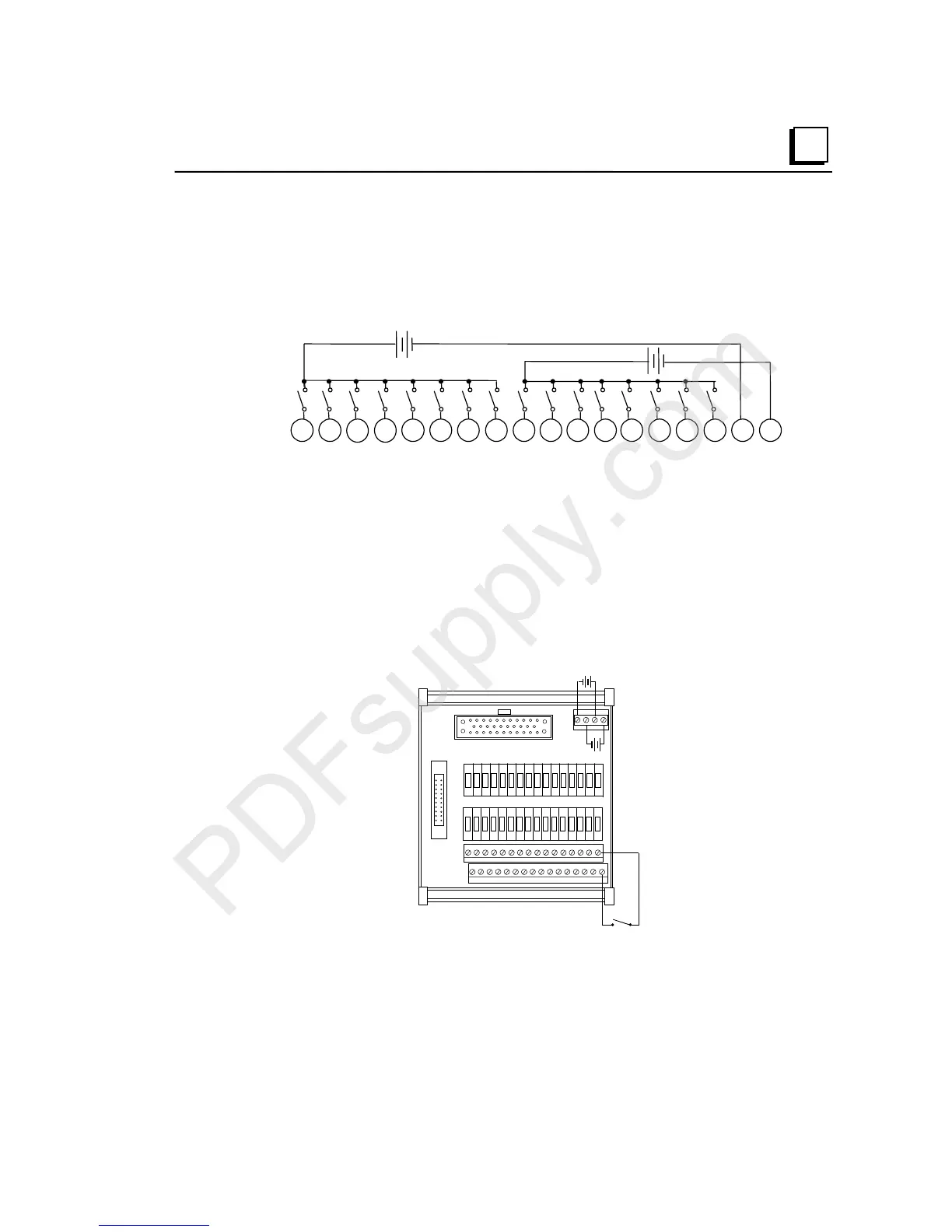
When connecting the Interposing Disconnect bases in this format, follow these guidelines:
Connect field devices to A1-A16 (or B1-B16 where appropriate)
Connect return wires of field devices to the corresponding common connections – A1
to W1, A2 to W2, A9 to X1, A10 to X2, etc.
Connect jumpers between the A17, W, and X terminals (or B17, Y, and Z).
Connect power supply between A17 and W (or B17 and Y).
Connect power supply between A18 and X (or B18 and Z).
Example Wiring Diagram for Module IC200MDL640
Example field wiring for IC200CHS101 when used with VersaMax modules with 2 groups
per terminal row
J1
J2
I1
A16A15A14A13A12A11A10A9A8A7 A6A5A4A3A2A1
X8 X7 X6 X5 X4 X3 X2 X1 W8 W7 W6 W5 W4 W3 W2 W1
A18 A17 X W

 Loading...


