GFK-1504K Appendix A Panel Mounting Dimensions A-11
A
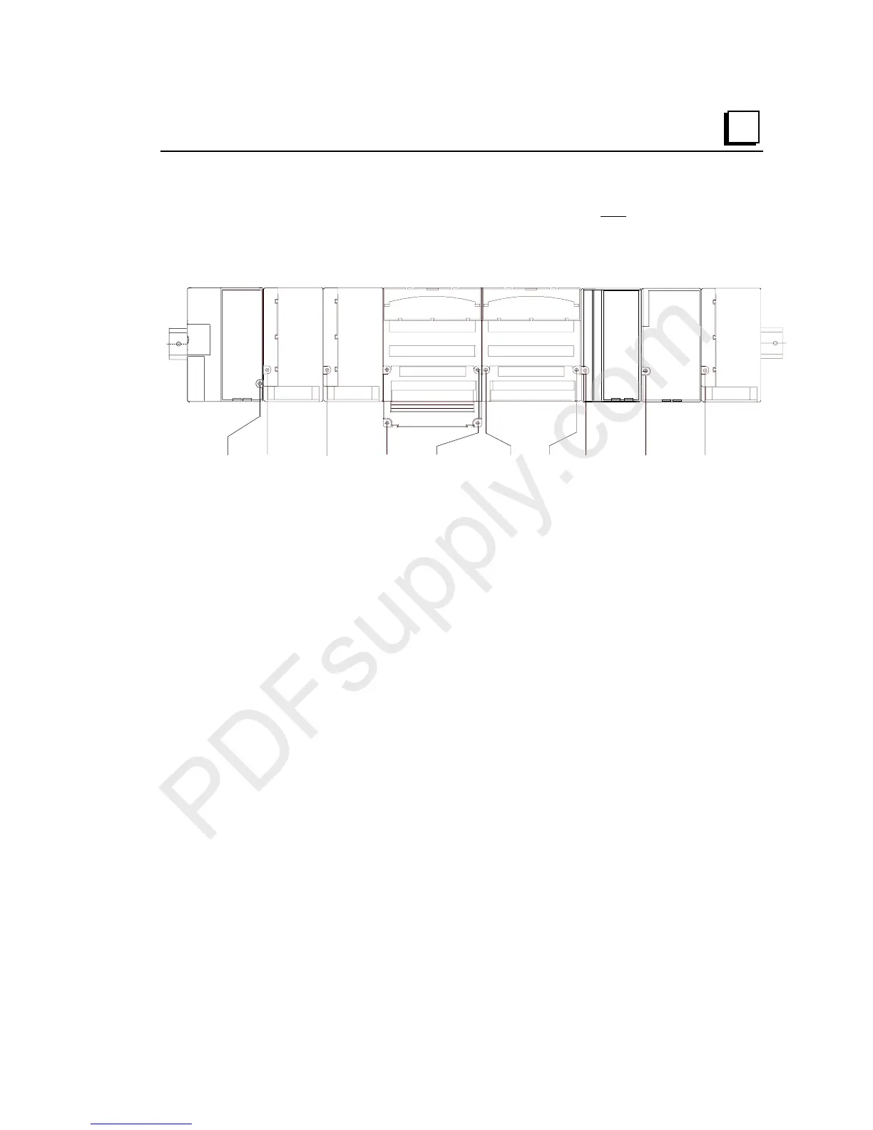
Example Mounting Dimensions
In an expansion system, the Expansion Transmitter Module adds 38.1mm (1.5in) to
the left side of the CPU or NIU in rack 0, represented below.
NIU (Shown) CPU,
or ERM Module
IC200CHS002
IC200GBI001
IC200PWB001
IC200CHS006
9.270in
235.5mm
9.610in
244.1mm
13.620in
346.0mm
5.260in
113.6mm
.000
2.630in
66.8mm
.340in
8.6mm
13.960in
354.6mm
16.590in
421.4mm
19.220in
488.2mm
IC200TBM002
IC200CHS002
IC200CHS003
IC200CHS003
IC200CHS003
Each expansion rack in an expansion system has an Expansion Receiver Module in
slot 0, with additional modules as shown above.

 Loading...


