2-8 VersaMax® Modules, Power Supplies, and Carriers User's Manual – March 2003 GFK-1504K
2
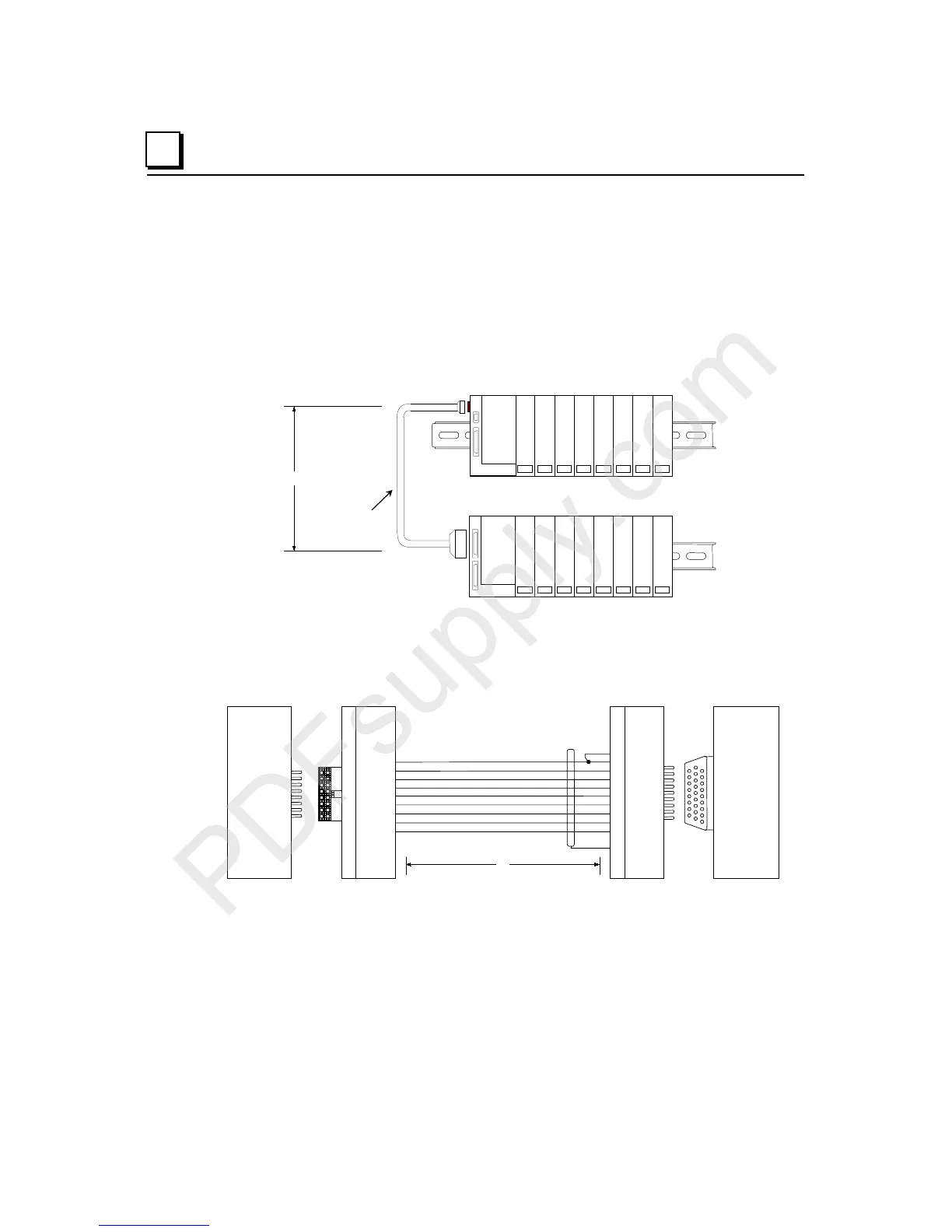
Connecting the Expansion Cable: Single-ended
For a two-rack local system with one non-isolated expansion rack (IC200ERM002) and
NO Expansion Transmitter, connect the expansion cable from the serial port on the
VersaMax CPU or NIU to the Expansion Receiver as shown below. The maximum cable
length is one meter. Cables cannot be fabricated for this type of installation; cable
IC200CBL600 must be ordered separately.
PS
ERM
VersaMax Expansion Rack
1 M
VersaMax PLC or NIU I/O Station Main Rack
PS
CPU/NIU
IC200CBL600
No Terminator Plug is needed in a single-ended installation; however, it will not impede
system operation if installed.
Single-Ended Inter-Rack Connection Cable (IC200CBL600)
PIN
1
2
3
6
9
10
12
16
14
0V
T_IOCLK
T_RUN
T_IODT_
T_RERR
T_RIRQ_
T_FRAME
T_RSEL
0V
PIN
16-PIN
MALE
16-PIN
FEMALE
26-PIN
MALE
26-PIN
FEMALE
1516
12
4
7
22
14
18
15
11
10
19
23
1
SINGLE_
0V
T_IOCLK
T_RUN
T_IODT_
T_RERR
T_RIRQ_
T_FRAME
T_RSEL
0V
SHIELD
1 M
Expansion
Receiver
IC200ERM002
Receiving
Port
VersaMax
CPU or NIU
Serial Port

 Loading...


