10-10 VersaMax® Modules, Power Supplies, and Carriers User's Manual – March 2003 GFK-1504K
10
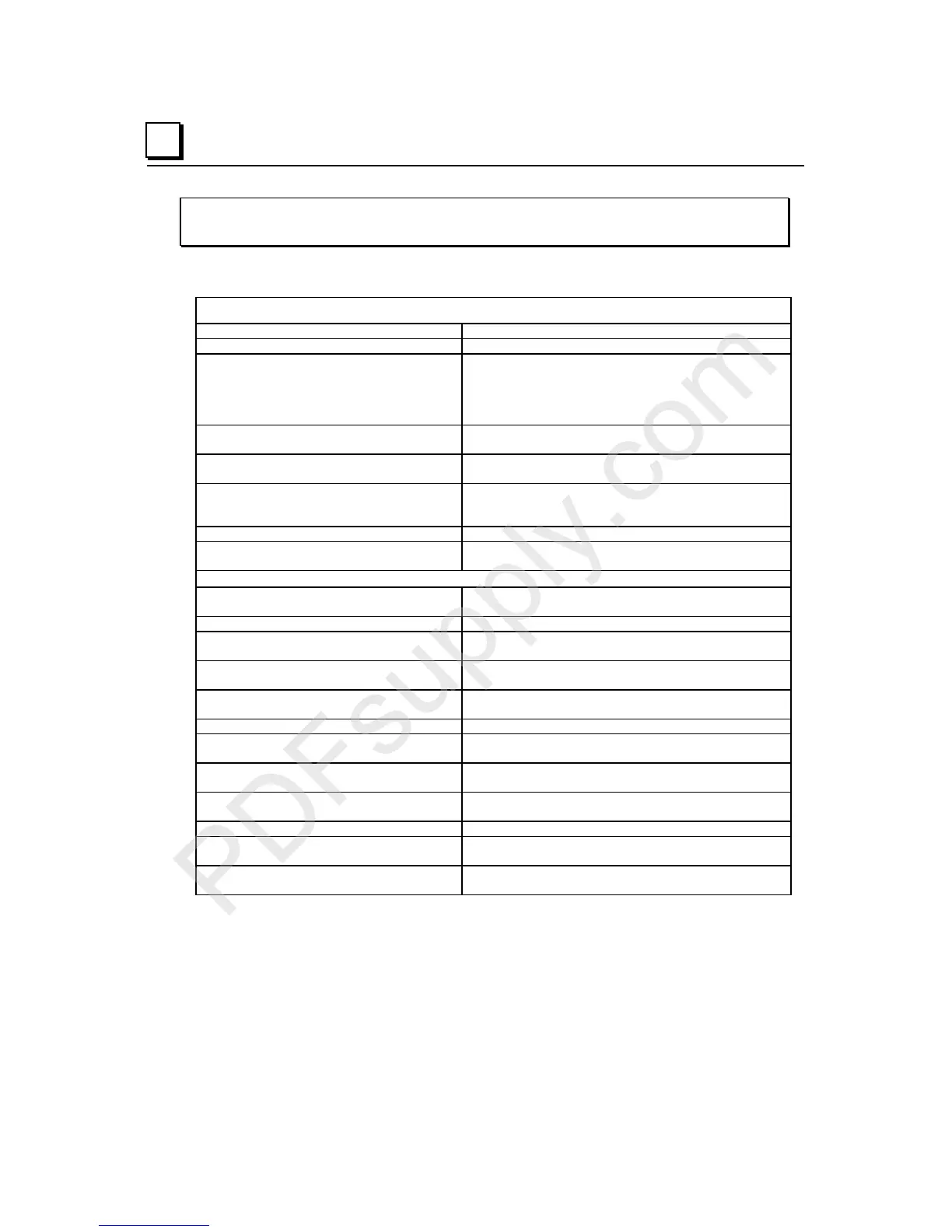
IC200ALG240
Analog Input Module, 16 Bit Voltage/Current, 1500VAC Isolation, 8 Channels
Module Specifications
Module Characteristics
Channels 8 inputs
Module ID FFFF9802
Isolation:
User input to logic (optical) and to frame
ground,
Group to Group
Channel to channel
250VAC continuous; 1500VAC for 1 minute
Not applicable
250VAC continuous; 1500VAC for 1 minute
LED indicators FLD PWR LED indicates the presence of both logic
power and user power. OK LED indicates module status.
Backplane current consumption 5V output: 15mA maximum.
3.3V output: 120mA maximum
External power supply:
Range
Current consumption
+19.5 to +30VDC including ripple
100mA maximum plus load currents
Thermal derating None
Diagnostics High/Low Limit, Over/Underrange, Open Wire, Loss of
Field Power Supply, Non-volatile memory fault
Input Characteristics
Input operating range Current mode: +1 to 20mA
Voltage mode: +/-10VDC
Accuracy at 25 degrees C +/- 0.1% maximum of full scale
Temperature coefficient Current mode: 45ppm/
°
C typical, 90 ppm/
°
C maximum
Voltage mode: 30ppm/
°
C typical, 60 ppm/
°
C maximum
Analog Resolution (1 LSB) Current mode: 381 nA nominal
Voltage mode: 381
µ
V nominal
Channel data Update rate per module Approximately 20 mS max. @ 50 Hz filter frequency
Approximately 16.7 mS max. @ 60 Hz filter frequency
Channel-to-channel crosstalk rejection 70dB minimum
Input default 0 (default)
Hold Last State (configurable)
Field input DC resistance Current mode:150 Ohms
Voltage mode:760 KOhms
Field input filter Type: Digital w/programmable notches at 50 or 60 Hz
3 dB Corner Frequency: 10Hz
±
25%
Normal mode (power line frequency) rejection 35 dB minimum
Field Input Ranges Current mode: Approximately 0 mA to +25 mA
Voltage mode: Approximately –12.5 V to +12.5 V
Maximum field input (without damage) Current mode:
±
35 mA continuous
Voltage mode:
±
17.5 V continuous

 Loading...


