1-10 VersaMax® Modules, Power Supplies, and Carriers User's Manual – March 2003 GFK-1504K
1
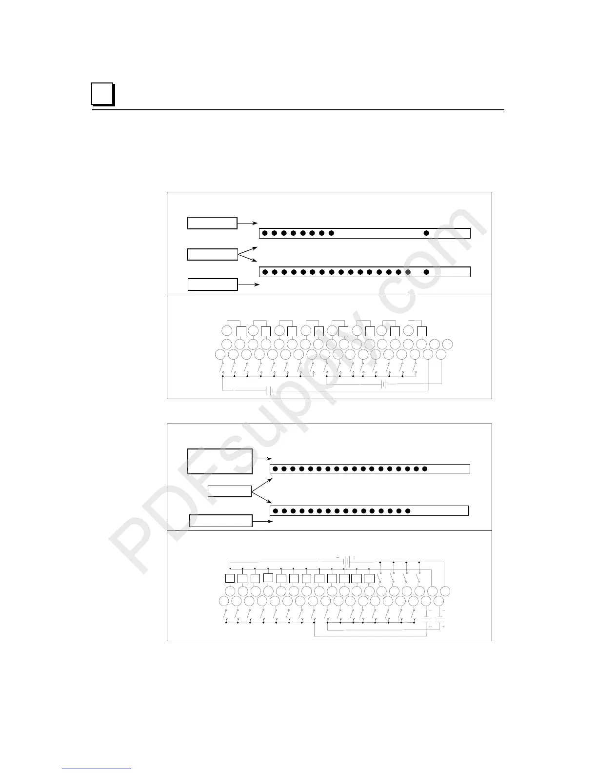
Discrete Module Point LEDs
Individual point LEDs on discrete modules provide status information at a glance.
Laser markings on the module identify the LEDs. The positions of the point LEDs always
correspond to the module’s wiring diagram, whether the module is simple:
LEDs for Discrete Mixed Module IC200MDD845
Q (output points)
Point numbers
I (input points)
123 456 78
12345678910
11
12 13 14 15 16
OK
Q
I
OK
Wiring Diagram for Module IC200MDD845
I1 I2 I3 I4 I5 I6 I7 I8 I9 I10
I11 I12 I13 I14 I15 I16
Q1 Q2 Q3 Q4 Q5 Q6 Q7 Q8
vv
v
vvvv v
1 2 3 4 5 6 7 8 9 11 12 13 14 15 16 17 18
123456789 111213141516171810
10
B
A
+
-
(+)
-
+
-
(+)
-
-
(+)
-
(+)
or more complex:
LEDs for Discrete Mixed High-speed Counter Module IC200MDD841
OK
1 2 3 4 5 6 7 8 9 10 1112 17181920
1 2 3 4 5 6 7 8 9 10 111213 141516
FLD
Q/I
I
Q (Output points 1 - 12)
followed by
I (input points 17 - 20)
Point numbers
I (input points 1 - 16)
Wiring Diagram for Mixed High-speed Counter Module IC200MDD841
1
A
B
2 3
4
5 6 7 8 9
1 2 3
4
5 6 7 8 9
11 12 13 14 15 16 17 18
11
12 13 14 15 16 17 18
10
10
I1 I2 I3 I4 I5 I6 I7 I8 9 I10 I11 I12 I13 I14 I15 I16
I17 I18 I19 I20
Q1
Q2 Q3
Q4
Q5 Q6 Q7 Q8 Q9 Q10 Q11 Q12

 Loading...


