GFK-1504K Chapter 2 Installation Instructions 2-5
2
Installing an Expansion Transmitter Module
An Expansion Transmitter Module must be installed to the left of a CPU or NIU.
1.
Make sure rack power is off.
2.
Attach the Expansion Transmitter to DIN rail to the left of the CPU or NIU.
3.
Slide the module toward the CPU or NIU and press together until the connectors are
mated.
4.
After completing any additional system installation steps, apply power and observe
the module LEDs.
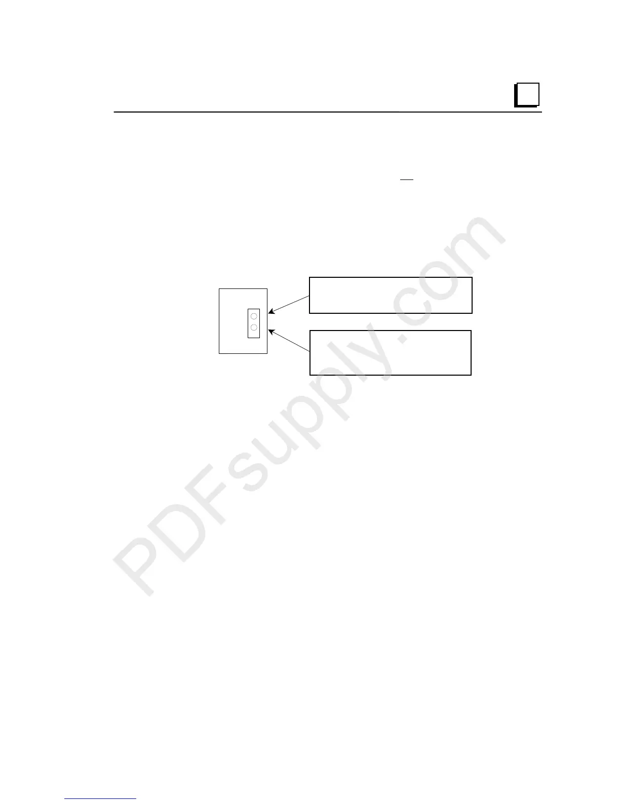
PWR
EXP TX
On indicates presence of 5VDC power.
Off indicates no 5VDC
ower.
Blinking or On indicates active
communications on expansion bus.
Off indicates no communications.
Removing an Expansion Transmitter Module
1.
Make sure rack power is off.
2.
Slide module on DIN rail away from the CPU or NIU in the main rack.
3.
Using a small screwdriver, pull down on the tab on the bottom of the module and lift
the module off the DIN rail.

 Loading...


