2-4 VersaMax® Modules, Power Supplies, and Carriers User's Manual – March 2003 GFK-1504K
2
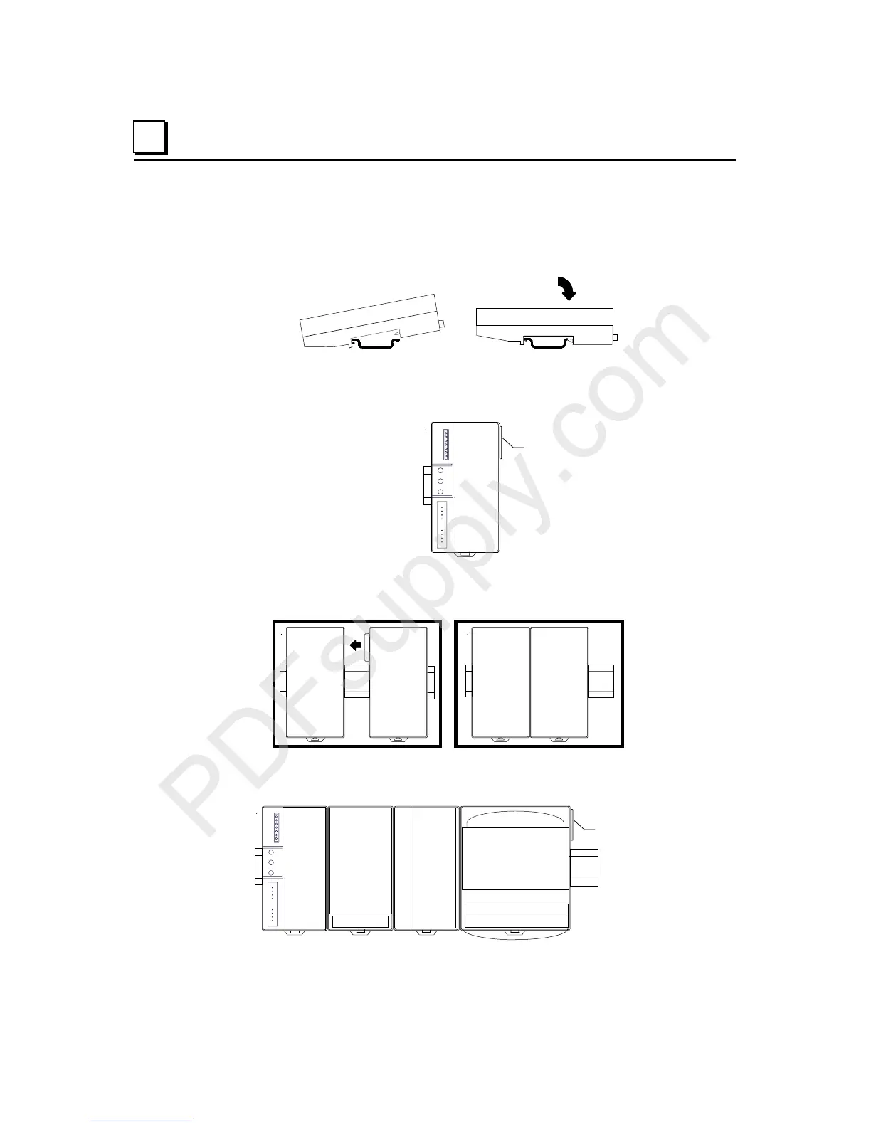
DIN Rail Installation Steps
VersaMax CPUs, Network Interface Unit (NIU) modules, Expansion Receiver (ERM)
modules, and module carriers snap easily onto the DIN rail. No tools are required for
mounting or grounding to the DIN rail.
Before joining module carriers to a CPU, NIU, or ERM, remove the connector cover on
the righthand side of the CPU, NIU, or ERM. Do not discard this cover; you will need to
install it on the last carrier.
Connector Cover
Slide carriers along the DIN rail to engage the connectors in the sides of adjacent carriers.
To avoid damaging connector pins, do not force or slam carriers together.
Install the connector cover that was removed over the connector on the last carrier to
protect the connector pins and to provide compliance with standards.
Connector Cover

 Loading...


