GFK-1504K Chapter 2 Installation Instructions 2-17
2
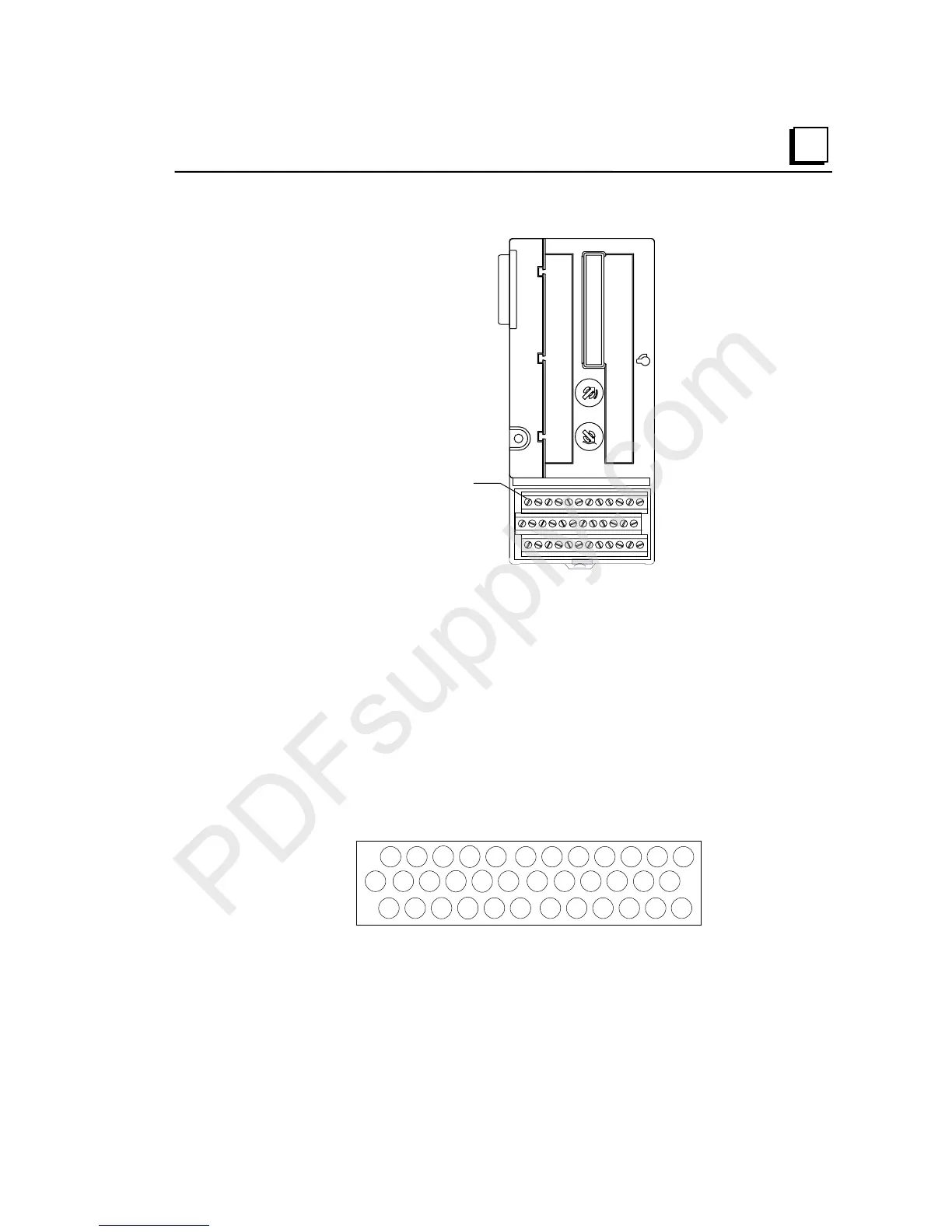
Wiring for a Compact I/O Carrier (IC200CHS022, IC200CHS025)
Field Wiring
T
rmin
l
Each terminal on a Compact-style I/O Carrier accommodates one solid or stranded AWG
#14 (avg. 2.1mm
2
cross section) to AWG #22 (avg. 0.36mm
2
cross section) wire, or two
wires up to AWG #18 (avg. 0.86mm
2
cross section). Use copper wire rated for 90 degrees
C. When inserting two wires in the same position, the wires must be the same size and type
(solid or stranded).
The I/O carrier can accommodate current levels up to 2 Amps per point or 8 Amps per
each power and ground, and a voltage range of up to 264 VAC. Voltage transients up to
300 VAC will not damage the carrier.
For a Box-Style I/O Carrier, recommended terminal torque is .37 to .45 ft-lbs.
The label provided with the module can be folded and inserted in the label holder.
Terminal Numbering for a Box- or Spring-Style Compact I/O Carrier
A1 A2 A3
A4
A5 B5 B6B3 B4B1 B2A6
A7 A8
A9
A10
B12B9 B10B7 B8A11 A12
A13
A14
A15
A16 B15 B16B13 B14
B17 B18A17 A18
B11

 Loading...


