4-12 VersaMax® Modules, Power Supplies, and Carriers User's Manual – March 2003 GFK-1504K
4
IC200CHS005
Spring-Style I/O Carrier
Din Rail Mounting
The carrier snaps easily onto a 7.5mm X 35mm DIN rail. The DIN rail must be electrically
grounded to provide EMC protection. The rail must have a conductive (unpainted)
corrosion-resistant finish.
For applications requiring maximum resistance to mechanical vibration and shock, the
carrier must also be panel-mounted. See chapter 2 for installation instructions.
Features
The Spring-Style I/O Carrier supports up to 32 I/O points and 4 common/power
connections.
Easily-set keying dials to assure installation of the correct type of module on the
carrier. Keys can be set to match the keying on the bottom of the module. A complete
list of module keying is included in appendix D.
Carrier-to-carrier mating connectors for quick installation of the backplane
connection with no additional cables or tools needed.
Module latch hole for securely fastening the module to the carrier.
A clear protective hinged door covering the wiring terminals. The printed wiring card
provided with each I/O module can be folded and inserted in this door.
Notches on the lower edge for attaching an Auxiliary I/O Terminal Strip if extra
bussed connection points are needed.
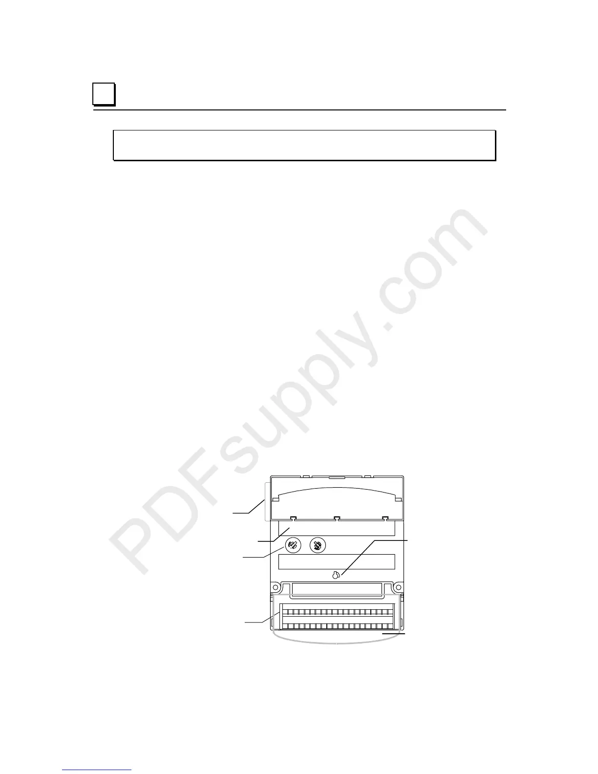
F
Module to Carrier
Connectors
Keying Dials
Field Wiring
Terminals
Transparent
rotective door
Carrier to Carrier
Connector
Module
latch hole
A
B

 Loading...


