8-34 VersaMax® Modules, Power Supplies, and Carriers User's Manual – March 2003 GFK-1504K
8
IC200MDL744
Output Module, 5/12/24VDC Negative Logic 0.5 Amp, 32 Points
Field Wiring
Terminal Connection Terminal Connection
A1 Output 1 B1 Output 17
A2 Output 2 B2 Output 18
A3 Output 3 B3 Output 19
A4 Output 4 B4 Output 20
A5 Output 5 B5 Output 21
A6 Output 6 B6 Output 22
A7 Output 7 B7 Output 23
A8 Output 8 B8 Output 24
A9 Output 9 B9 Output 25
A10 Output 10 B10 Output 26
A11 Output 11 B11 Output 27
A12 Output 12 B12 Output 28
A13 Output 13 B13 Output 29
A14 Output 14 B14 Output 30
A15 Output 15 B15 Output 31
A16 Output 16 B16 Output 32
A17 DC - B17 DC -
A18 DC + B18 DC +
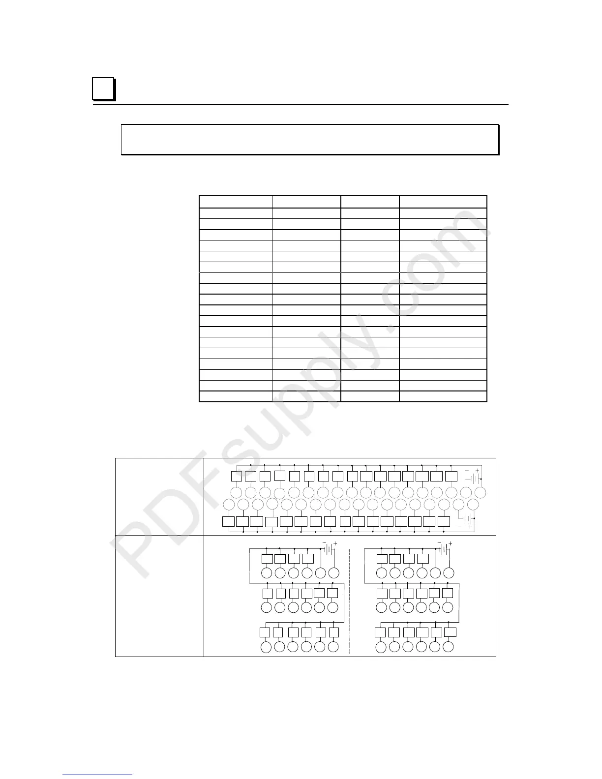
The 32 outputs form two groups, each with a DC+ and a DC- terminal.
When wiring outputs to inductive loads, use of external suppression circuits is
recommended. See chapter 2, "Installing Wiring for I/O Devices-Wiring to Inductive
Loads" for more information.
Wiring Connections
for Carriers with Two
Rows of Terminals
IC200CHS002, 005
IC200CHS012, 015
Q1
Q2 Q3
Q4
Q5 Q6 Q7 Q8 Q9 Q10 Q11 Q12 Q13 Q14 Q15 Q16
1 2 3 4 5 6 7 8 9 11 12 13 14 15 16 17 1810
A
Q17 Q18 Q19
Q20
Q21 Q22 Q23 Q24
Q25 Q26
Q27
Q28 Q29 Q30 Q31 Q32
1 2 3 4 5 6 7 8 9 11 12 13 14 15 16 17 1810
B
Wiring Connections
for Carriers with Three
Rows of Terminals
IC200CHS001, 022, 025
IC200CHS011
A
123456
13
14 15 16 17 18
789 111210
Q1 Q3
Q7
Q15
Q5
Q9
Q11
Q13
Q2 Q4
Q8
Q16
Q6
Q10
Q12
Q14
B
123456
13
14 15 16 17 18
7 8 9 11 1210
Q17 Q19
Q23
Q31
Q21
Q25
Q27
Q29
Q18 Q20
Q24
Q32
Q22
Q26
Q28
Q30

 Loading...


